Wednesday, April 22, 2015
Gqrx SDR
Practical tricks and tips
Written by Robert Lainé (robert.laine at sailcut.com), this document provides a practical introduction to getting started with gqrx.
Table of contents
Gqrx is a software defined radio (SDR) receiver written by Alexandru Csete to control and use a variety of SDR hardware. The following describes the procedure to install gqrx and use it with a FunCube Dongle Pro+ receiver on an Asus Eeepc-1200 NoteBook setup withLinux Debian 8 and KDE. Earlier versions of Debian come with an older version of gqrx that may not have all the features described here.
Installation
In order to use gqrx you will need to install gnuradio and gqrx packages with the following command for Linux Debian:
$ sudo apt-get install gnuradio gqrx
Once gnuradio and gqrx are installed (above procedure depends on which OS you are using):
- Connect the FunCube Dongle Pro+ receiver to the PC USB-2 port (do not use a USB-3 port as it may not work reliably on all PC). Use an USB extension cable for the connection to the PC to distance the receiver from the PC (hefty source of noise) and minimise the mechanical loads applied to the dongle connectors.
- Connect the antenna to the female SMA connector of the FunCube dongle. For HF and VHF, I found it convenient to use 1m of RG-174 coax terminated at one end with a male SMA and a male BNC at the other end such that I can reuse my HF antenna tuning box.
Starting gqrx
Having the device connected to the PC and the appropriate antenna, open a terminal and launch gqrx with the line command:
$ gqrx
The first window to appear is for configuring the Input/Output of the device:
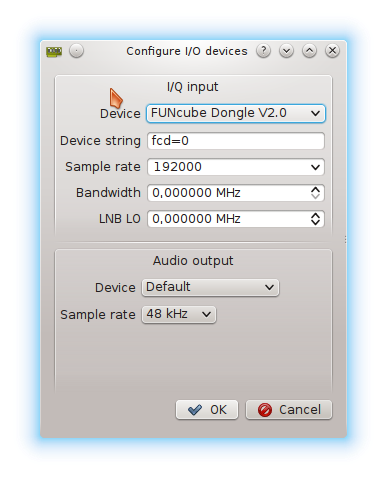
I/O device configuration dialog
Make sure that the Device line shows the FunCube Dongle or the device you are using. Leave the other fields as they are then click OK. The main window of gqrx looks as below.
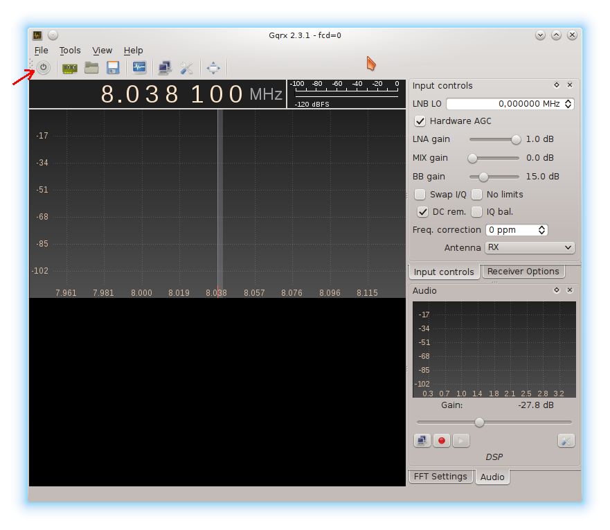
Gqrx main window.
Activate gqrx by clicking on the grey start/stop button just below the File menu (see the red arrow pointing at the start/stop button). The central window should show something like below, and noise should be heard from your speaker or head-phones, if not, check your audio volume control.
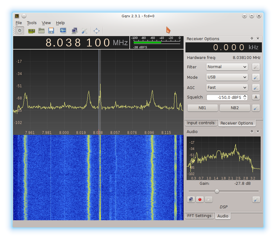
Gqrx main window while the application is running
Using gqrx
The upper part of the gqrx window proposes various roll-down menus:
- File
- Tools
- View
- Help
Below these menus you find a number of short-cut buttons:
- Start/stop (already used)
- Configure I/O devices
- Load previously stored configuration
- Save current configuration
- Record and Play I/Q data
- Configure remote control settings
- Toggle full screen
In the left part of the main window starting from the top you find:
- The current frequency of the receiver (here 8.038 100 MHz).
- Below the frequency is the RF spectrum frame around that frequency.
- Below the spectrum frame is the waterfall frame displaying the spectrum history.
On the upper right side of the main window you will find frames with tabs for the input and options of the Receiver, and lower right side frames with tabs for RF signal processing (FFT Settings) and Audio output control.
The color of the spectrum display can be changed by the “color” line of the FFT setting tab.
Tuning the receiver
To tune the received frequency move the mouse pointer on any of the frequency digits and use the mouse wheel to change it. Alternatively you can move the pointer and click on the upper or lower part of any digit or use the Up/Down key to change it.
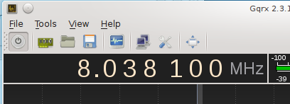
Gqrx toolbar and main frequency control widget
Note that there is a second frequency displayed on the right frame of “Receiver Options” tab. It display the offset of the actual frequency from the central line of the main display frequency. Keep it to 0.000 until you are familiar with all the functionalities of gqrx.
Receiver options
In the Upper right window appears either the Receiver Options or the Input controls depending on which tab you clicked on, as shown below:
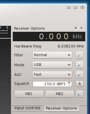
Gqrx receiver options
The frequency windows allows you to offset the receiver actual frequency from the main frequency entered in the left window. It can be useful for e.g. weather fax reception as the frequency to be used is normally 1.9 kHz below the nominal frequency of the station. Personally, I prefer to keep that offset frequency to 0.00 and set the main frequency.
Filter and mode go together. Here it is shown for receiving weather fax, in USB and a Normal filter.
Mode setting is for the modulation mode of the signal received, it can be:
- CW-U or CW-L for Morse code On-Off modulation (use Upper or Lower side band depending on possible interference from another carrier close by)
- USB or LSB for single side band amplitude modulation, Upper or Lower Side Band,
- WFM (stereo or mono) for Wide Frequency Modulation used by broad casting stations,
- Narrow FM for e.g. marine VHF,
- AM for old style Amplitude Modulation used by broadcasting stations,
- Raw I/Q is intended to pass raw I/Q data through without any demodulation; however, this mode has not been implemented yet,
- Demod Off essentially turns off all signal processing. Gqrx can then stil be used to view the real time spectrum.
Filter can be Normal, Narrow, Wide or user set. Narrow filters are useful against interference from stations on nearby frequencies but they also require more CPU power. The same applies for the filter shape: A filter with sharp edges will be better against interference but requires more computing.
AGC can be set to Off, User, Slow, Medium, Fast. Choose whichever best fit the current propagation fading. I tend to use the “Fast” AGC mode.
Squelch control is mainly used when you want to monitor a fixed frequency, for example channel 16 (156.8000 MHz) of marine VHF or the local airport frequency. You can change the squelch level by entering the appropriate value in the line to the right of “Squelch” or you wait for a period when nobody is talking and click on the button A to right of the squelch level and it will automatically adjust the squelch level to that of the current background noise. Do not forget to lower again the squelch level when you change frequency or mode.
NB1 and NB2 activate noise blankers for attenuating static and pulse type noise.
Input controls frames
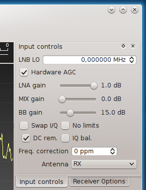
Gqrx input controls
At the top there is a frame LNB LO for entering a “Local Oscillator” frequency in case to use an up or down converter in front of your SDR dongle. In all other cases keep it to 0.000000 MHz.
Hardware AGC: Some hardware has built-in automatic gain control in either the RF front end of the IF stages. It saves fiddling with the various manual gain settings. In some cases where you have serious interference from a local “jammer” you may have to switch off the AGC and tweak the various gains. Start by lowering the LNA and Mixer gain and look at the effect on the RF spectrum.
Swap I/Q: Swaps I and Q channels, normally you want to to leave it off.
No limits: Leave it off, it is only if you want to use the sdr beyond its recommended frequency domain.
DC rem.: Tick it, it removes the DC bias often seen in direct conversion receivers.
IQ bal.: leave it off unless you have ghost images in the spectrum.
Freq. Correction: a very useful feature to correct the error or drift in the dongle internal oscillator. To do that you need to tune to the nominal frequency of a the carrier of very well known station or even better to the frequency of a reference generator, then you adjust “Freq.correction” until the displayed frequency of the main window correspond to that of the reference signal. Remember that 10ppm is 10Hz of a 1MHz signal, 1.44kHz of a 144MHz signal, etc.)
Once you have corrected the frequency, save the settings with the File → Save settings menu (in Debian KDE these are save to ~/.conf/gqrx/default.conf) and write down the number of ppm entered in you preferred logbook together with the SDR device model/serial number such that you can monitor future drift or use it next time to use the SDR dongle on a different PC.
Antenna: keep it to Rx, anyway there is no other option for the FunCube Dongle.
Audio and FFT signal processing options frames
Audio and FFT signal processing options frames
Audio frame
In the lower right window appears either the spectrum and controls of the Audio signal received or the FFT Settings depending on which tab you clicked on.
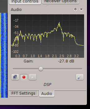
Gqrx audio options
The Audio spectrum frame shows the spectrum of the demodulated signal. You can change the scale of the spectrum by click and drag the mouse pointer of the frequency scale, and move it right-left with the mouse wheel.
The slider below the audio spectrum control the output level to the speaker/headphone.
The Tool button (lower right) opens a window with a tab Recording in which you can change the directory in which gqrx will save audio signal received in a .wav file.
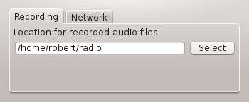
Gqrx audio recording options
The audio file name format will be: gqrx_yyyymmdd_hhmmss_frequency.wav
- yyyy is the year
- mm is the month
- dd is the day
- hhmmss the start hour, minutes,seconds
- frequency is the hardware in Hz
The Network tab allows you to change the network port number to which the audio is sent.
FFT Settings frame
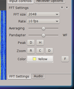
Gqrx FFT settings
The FFT Size is the number of points used in the FFT calculations. It determines the resolution of the plot. For example, if the bandwidth is 192 kHz and FFT size is 4096, then the FFT resolution is 192000 / 4096 = 46.875 Hz / FFT bin. An additional scaling takes place to convert from FFT bins to screen pixels.
FFT Averaging is used to reduce the noise level. Gqrx uses adaptive averaging where the averaging factor depends on the signal level. This results in the noise floor being averaged more than strong signals enahncing the visual experience. The averaging only affects the FFT plot / pandapter and not the waterfall.
The Pandapter ⇔ WF slider allows to modify the portion of the main display allocated to the spectrum and to the waterfall.
The Peak “D” button will attach little circles to the peaks of the RF spectrum display.
The Peak “H” buttons will display faintly the envelope RF spectrum.
The Zoom “R”, “C”, “D” buttons are respectively for:
- R = resetting the RF spectrum display to its 100% default value,
- C = centering the RF spectrum display around the original frequency
- D = centering the RF spectrum display around the demodulator frequency
The Color selector changes the color of the RF spectrum display.
The “F” button will fill / clear the space below the spectrum line with a color gradient.
Refined settings
Changing the RF spectrum display
You can change the frequency scale by placing the mouse pointer on the frequency scale at the bottom of the spectrum window and then click+drag right or left or using the mouse whell to stretch the display. You can reset the display with the “Zoom” “R” button in the FFT Settings frame.
Changing the Receiver filter (user defined)
In the spectrum window, the grey band represent the width of the receiver filter. Its width depend on the Receiver Option chosen for the filter, here it is shown set as “normal”.
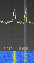
Gqrx filter adjustment
You can also adjust the filter as you like by the following procedure:
- Make sure you have the Audio spectrum displayed such that you can “see” what you are doing.
- Move the mouse pointer over the grey band representing the current filter.
- Press and hold CTRL key + mouse wheel: change filter width
- Press and hold SHIFT key + mouse wheel: change filter offset (to eliminate a spurious signal close to the carrier). The effect will be seen in the Audio spectrum as a dip starting at the low frequencies)
Alternatively you can move the mouse pointer over the right edge of the grey band until it changes to an inclined double arrow, click and drag it. Same procedure to click and drag the lower frequency edge of the filter but much more difficult as the mouse pointer tend to grab the center frequency of the receiver rather than the lower edge of the filter. It sometime help to offset the receiver frequency from the central line by adding a few kHz in the Receiver Options frequency window.
Configure I/O devices
With the FunCube Dongle Pro/Pro+ there is nothing to change.
TODO: explain the various settings for the RTL-SDR dongle.
Applications
Receiving weather faxes
I use the FunCube Dongle Pro+ to receive weather faxes from Northwood UK. These are transmitted starting after the hour, simultaneously on the following frequencies:
| Nominal frequency | Set gqrx to (+USB) | Notes |
|---|---|---|
| 2618.5 kHz | 2616.6 kHz | 2000-0600 UTC |
| 4610.0 kHz | 4608.1 kHz | 0000-2400 UTC |
| 8040.0 kHz | 8038.1 kHz | 0000-2400 UTC |
| 11086.5 kHz | 11084.6 kHz | 0600-2400 UTC |
The transmission is AM Upper Side Band and the weather picture modulation is using 2 tones at 1500 Hz (black) and 2300 Hz (white).
It is necessary to set the receiver 1.9 kHz below the nominal frequency of the transmitter and set the Receiver options Mode to USB with a Filter to Normal. Also make sure that you have set the Audio recording destination to a directory which is easily accessible.
Once you get the start tone of the transmitter, immediately press on the Audio RECbutton to start record the demodulated signal, and wait for 11 minutes until the end of transmission. Meanwhile you can listen to the “music of the image” and very quickly you will recognise its various phases, in particular the end of image multi-tones. At this point in time you can press again on the Audio red button to stop the audio recording. Be ready for the next transmission which may starts about 45s after the end of a previous image.
Once you have recorded an image you can visualise it with another sotware named hamfax written by Christof Schmitt, DH1CS, which is part of Debian distribution. You can install it using:
$ sudo apt-get install hamfax
Launch hamfax and click on the “Receive / Recevoir” tab at the top and make sure the “receive from audio peripheral” option is selected. Note that my installation of hamfax is in french, english text should be easily understood.
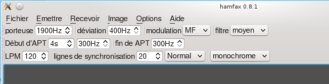
Hamfax main screen
Open the audio file recorded with for exemple VLC and start playing it back. Monitor the audio level received by hamfax in the horizontal sub-window, and adjust the audio mixer such that the level is as high as possible but below continuous saturation. It can happen that your audio mixer is set to a low level for the gqrx output. Adjust it before you start recording.
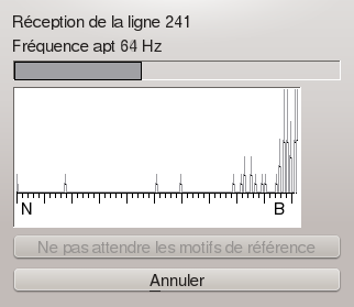
Hamfax start/stop
If for any reason hamfax did not start decoding the picture, it is most likely that you started to late recording the audio signal from gqrx and missed the syncronisation phase. The image is not all lost, it may just be truncated at the beginning! Just restart playing it back and use the “Skip/Annuler” button to launch the decoding without waiting the APT and Synchronisation phase.
Once the image is complete (it takes about 12 minutes) use the“Skip/Annuler” button to stop hamfax. The screen will most likely look like below:
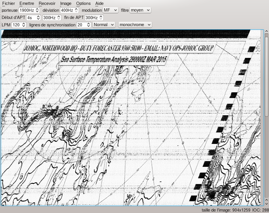
Hamfax decoded image
To correct the image slant use the “Image” menu and its correct slant option. After that you may still have to correct the position of the beginning of the lines, again with the appropriate option of the “Image” menu.
The result should look like below:
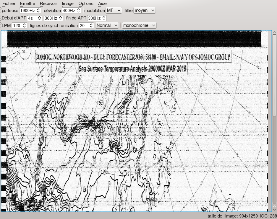
Hamfax slant corrected image
The horizontal grey lines are due to noise from poor reception of the signal. Some image processing can be use to remove that noise, if necessary.
Finally save the decoded image for further processing. Note that by default hamfax save the image as yyyy-mm-dd-hh-mm-ss.png.png and it is easy to find them in the directory from which you launched hamfax.
I find that the stored images are too stretched in the vertical dimension for reading them on the screen. I correct the vertical size with imagemagick tool “convert” as follow:
First find the size of the image:
$ file 2015-03-29-17-28-33.png.png
it will return something like:
2015-03-29-17-28-33.png.png: PNG image data, 904 x 1259, 8-bit/color RGB, non-interlaced
The PNG image is 904 pixel wide by 1259 high. Given the format of the fax transmitted should be about 904×638, use the following command to resize the image and remove one of the png extension such that it does not overwrite the original:
$ convert 2015-03-29-17-28-33.png.png -resize 904x638\! 2015-03-29-17-28-33.png
Notes on weather faxes reception problems encountered with a laptop:
- Both gqrx and image decoder process signals in real time. Some laptops have a somewhat slow processor and if you try to use gqrx simultanously with a fax decoder like hamfax (fldigi is another fax decoder and it shows similar issues) then the image received may have lines which are offset from their normal position. This is due to time delays in the signal processing when the processor become overloaded. I found that having gqrx working alone and recording the image and then processing it with hamfax after I have finished receiving all images gives much better images quality.
- Laptops have a built in microphone and loudspeaker and when paying back the audio it can happen that the output of the loudspeaker is heard by the microphone and mixed with the audio stream picked up by hamfax or other fax reader. Obviously that degrades the quality of the image and it shows up as shadow to the right of the image! On my Asus EeePC, the only solution to get rid of this issue is to disconnect the internal microphone by plugging a dummy mic into the microphone jack. One could also use a headphone plugged into the corresponding jack to disconnect the internal loudspeaker but that still leaves the internal microphone on and it will pick up ambien noise, furthermore you will then not hear the “music of the image”!
Tuesday, April 14, 2015
Tinkering with the Credit Card Crystal Radio
A few weeks ago, we published a short post about a credit card crystal radio from an eBay seller in the UK.
I purchased a kit–at $17-18 US shipped, it’s quite a modest investment for what might be a fun little project.
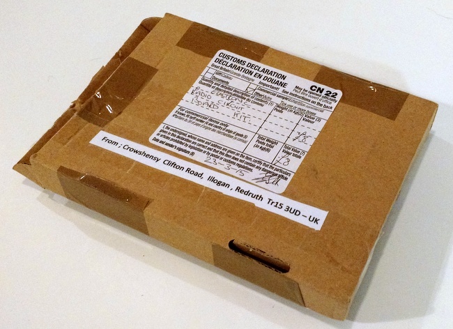
The crystal radio arrived while I was traveling during Easter break, but my free time has been so (extremely) limited lately, I was only able to unpack and try out this new arrival yesterday.

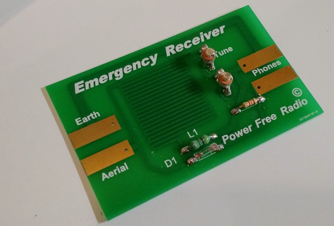
The biggest surprise for me was the fact that this isn’t really a kit–the board is fully populated and requires no soldering whatsoever. The board feels of very good quality.
All that is required is connecting the high-impedance earphone, earth/ground and aerial/antenna to the board. Since all of these components can be connected with the supplied alligator clip cables, getting it on the air took all of 20 seconds. I simply hooked up the ground and connected the aerial to my sky loop wire antenna.
I instantly heard a signal and station ID which confirmed it was our closest local broadcaster on 1010 kHz. This station isn’t of the blowtorch variety, but is the strongest one I receive on the MW band simply due to its proximity. Audio was quite faint through the earpiece, but I believe if I tinkered with antenna length and the two variable capacitors, I could improve reception.
SWLing Post reader, Richard Langley, received his crystal radio and had a very similar experience with reception.

With any crystal radio (especially one this small), performance is directly correlated with antenna length, availability of a good ground connection and, of course, strong broadcasters in your vicinity.
I plan to spend an evening tinkering with this little receiver and see if I can pick up some of the night time powerhouse AM stations on the east coast.
I can say this: if you’re looking for a simple, uber-compact emergency receiver for your go-bag, bug out bag or emergency kit, this one will certainly fit the bill. This crystal receiver and all of its components weight no more than a few ounces and could easily fit in compact pouch or sleeve.
Have any other readers have enjoyed tinkering with this little emergency crystal radio?
If you would like to purchase one, try searching eBay with one of the links below. The product will only appear in the search results if currently available.
Friday, April 3, 2015
TOTAL ECLIPSE OF THE MOON
From Spaceweather.com.
On Saturday morning, April 4th, the shadow of the Earth will fall across the Moon, turning the lunar disk a beautiful shade of celestial red. The total eclipse will be visible from the Americas, the Pacific Ocean, Australia, New Zealand and eastern parts of Asia. Click to preview the Moon's colorful transformation:

Some total eclipses last for more than an hour. In this case, however, totality spans just 4 minutes and 43 seconds—a result of the fact that the Moon is skimming the outskirts of Earth's shadow rather than passing centrally through it. The brevity of the eclipse highlights the importance of watching the clock: Be outside no later than4:58 AM PDT (11:58 UT) to witness the red Moon.
Why red?
A quick trip to the Moon provides the answer: Imagine yourself standing on a dusty lunar plain looking up at the sky. Overhead hangs Earth, nightside down, completely hiding the sun behind it. The eclipse is underway. You might expect Earth seen in this way to be utterly dark, but it's not. The rim of the planet looks like it is on fire. As you scan your eye around Earth's circumference, you're seeing every sunrise and every sunset in the world, all of them, all at once. This incredible light beams into the heart of Earth's shadow, filling it with a coppery glow and transforming the Moon into a great red orb when viewed from Earth.
Red is not the only color, however. Sometimes observers spot a subtle band of turquoise:

This is the "ozone fringe." Atmospheric scientist Richard Keen of the University of Colorado explains: "Most of the light illuminating the Moon passes through the stratosphere, and is reddened by scattering. However, light passing through the upper stratosphere penetrates the ozone layer, which absorbs red light and actually makes the passing light ray bluer." This can be seen using binoculars or a small telescope as a turquoise border around the red. Be alert for both colors on Saturday morning!
Wednesday, April 1, 2015
Two Brother and the Ultimate Willys Jeep Collection
This collection of Willys Jeep vehicles is owned by my brother and I. We have 20 total running/restored, several still works in progress, not included in the 20. Also several Wranglers, Cherokees, and J-10 Pick Ups. My farm is in Bishopville MD 2 miles south of the Delaware line, 3 miles off the atlantic coast, (Ocean City Md.) We got our first CJ-3A in ’59, I was 11. I took my drivers test in it in ’64. We have bought and restored these things since the late 60’s. Bought a few that were done, semi done and basket cases. I do aircraft for a living, Jeeps, classic chevys and corvettes as a hobby. My brother sells rollbacks and wreckers for a living. BTW the blue CJ-5, 4th from the left is a ’72. I know, a AMC. Fact is it is the first new vehicle I ever bought. Jan of ’72. Never been painted, original interior, 44,000k. Of course I took the 304 and T-15 out and put a 401 and a super T-10 in it. Young and Dumb. The ’72 is still pristine. There is a story behind each one of them so I will just share the story of my 1963 Willys Station Wagon right now…


 Bought it in 1974 at a government auction for $475.00. Replaced the blown OHC 6 with a 327 chevy mated to the T-90. The Jeep was equipped with heavy springs,two fuel tanks and a posi 4:10 rear. It was gun metal grey. I repainted it in 1978 using ’78 chrysler colors, Metallic silver and charcoal metallic. The interior was also repainted and the upholstery replaced with black roll & pleat. Refinished the wooden planks on the floor also. As fuel prices increased I replaced the 327 with a 9-1 comp. 355 Chevy that I put together with a Sig Erson RV cam ,etc. Replaced the T-90 with a Muncie 4 speed, Hurst shifter and a warn overdrive. All the windows, window seals, sheet metal, floorboards are original. It had a small amount of rust damage on the lower rocker below the doors on both sides which I corrected in ’78. I used to drive it to work daily prior to repainting in 1978. It know lives in my garage with my other Jeeps. It has just turned over 80,000 miles. This Willys is a true survivor. I live on the eastern shore in lower Delaware. This October, Ocean City Maryland had their first “Jeep Week”, I took the old wagon there to my surprise it won Best in Show. Not bad for something that was repainted 32 years ago. When I take the Station Wagon out it turns alot of heads. Some ask “what is that thing”. As it is pictured it runs down the road at 55-60 mph, turning around 2100 rpm. A joy to drive even with the original steering. I’d like to add that my first Jeep was a 1949 CJ-3A that my dad bought used in 1959. I was 11 at the time and learned to drive in that Jeep. Took my drivers test in ’64 in that thing, like a dummy I sold it in 1972 when I bought my first new vehicle which was a ’72 CJ-5. Still have the ’72, 42,000 miles original “Jetset Blue ” paint and interior. Replaced the 304 & T-15 with a 401 & super T-10.


Bought it in 1974 at a government auction for $475.00. Replaced the blown OHC 6 with a 327 chevy mated to the T-90. The Jeep was equipped with heavy springs,two fuel tanks and a posi 4:10 rear. It was gun metal grey. I repainted it in 1978 using ’78 chrysler colors, Metallic silver and charcoal metallic. The interior was also repainted and the upholstery replaced with black roll & pleat. Refinished the wooden planks on the floor also. As fuel prices increased I replaced the 327 with a 9-1 comp. 355 Chevy that I put together with a Sig Erson RV cam ,etc. Replaced the T-90 with a Muncie 4 speed, Hurst shifter and a warn overdrive. All the windows, window seals, sheet metal, floorboards are original. It had a small amount of rust damage on the lower rocker below the doors on both sides which I corrected in ’78. I used to drive it to work daily prior to repainting in 1978. It know lives in my garage with my other Jeeps. It has just turned over 80,000 miles. This Willys is a true survivor. I live on the eastern shore in lower Delaware. This October, Ocean City Maryland had their first “Jeep Week”, I took the old wagon there to my surprise it won Best in Show. Not bad for something that was repainted 32 years ago. When I take the Station Wagon out it turns alot of heads. Some ask “what is that thing”. As it is pictured it runs down the road at 55-60 mph, turning around 2100 rpm. A joy to drive even with the original steering. I’d like to add that my first Jeep was a 1949 CJ-3A that my dad bought used in 1959. I was 11 at the time and learned to drive in that Jeep. Took my drivers test in ’64 in that thing, like a dummy I sold it in 1972 when I bought my first new vehicle which was a ’72 CJ-5. Still have the ’72, 42,000 miles original “Jetset Blue ” paint and interior. Replaced the 304 & T-15 with a 401 & super T-10.
Kaiser Willys Jeep Blog Story – Rob Danzi
If you would like to share your Willys Jeep Story please send us a line. We ‘d love to meet your Jeep.
Subscribe to:
Posts (Atom)