In May, I discovered via a newsletter that a new kit was available from Javier EA3GCY in Spain. I was immediately sold as this was a kit from my favourite kit producer and it has 2 bands–it will also be able to do CW and there also will be a CW filter.
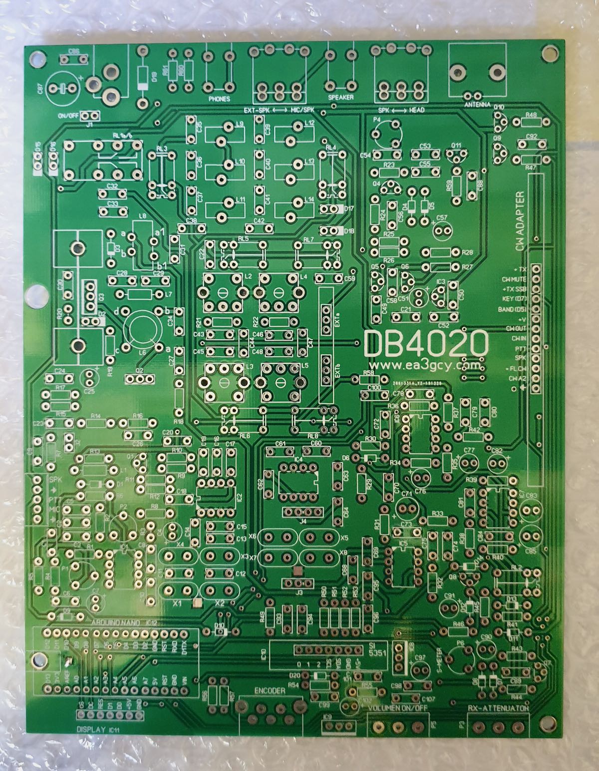
After building 2 MFT’s from Javier which work without problems, I needed to have the DB4020. The MFT’s are for 20 and 40 mtrs and do DSB (double side band). I did put them in a not-so-graceful box but they do what they are intended for which is QRP phone (SSB). They came together without problems so I expected the same for the DB4020–I knew for sure when I saw the board: all through-hole components (except for some capacitors which are factory soldered) and a lot of space on the board. The board has been silk-screened with clear indications on where all components have to come and the manual has very clear instructions where each component has to be soldered with referral to a quadrant. The manual provides a 252 quadrant page so it is a piece of cake to find where each piece goes.
What do you get?
Javier provides you with all components which need to be installed on the board and, of course, the kit board. The components come in small marked plastic bags and all is well-wrapped up in bubble wrap. The board is wrapped separately and that is put together with the component wrap which is then again wrapped up in bubble plastic. All goes into an envelope. Very well packed I must say.
Here’s a picture of the bags with components:
The silk-screened board:
I started with the resistors since that’s the easiest way. After that, I did the capacitors. I like to solder in all flat components first, so next were the diodes and IC sockets followed by the elco’s. The transistors were next together with all relays. As you solder in the transistors one also has to mount the cooling heatsinks, these cooling sinks are high and are ideal to protect the coils one has to make, they also protect the polystyrene caps (which I always find vulnerable) when the board is upside down.
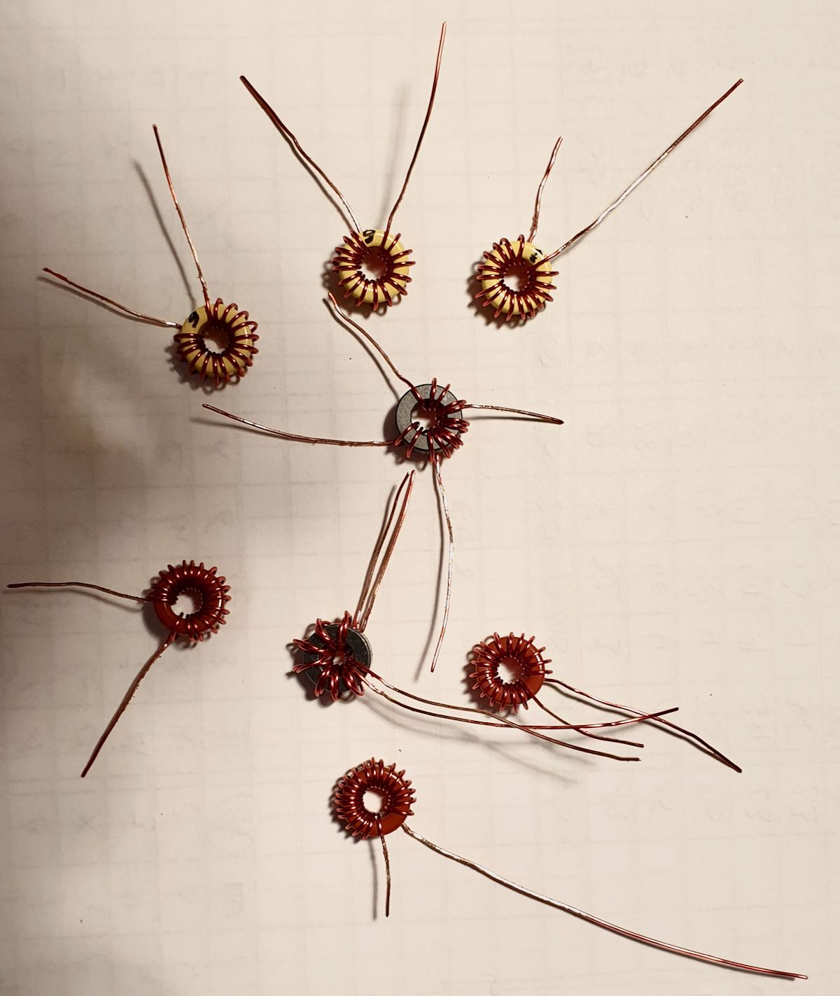
Many kit builders are afraid of winding the toroids in kits–don’t be! It is easy. Just take your time and follow the instructions given by Javier in the construction manual. In this kit the builder has to wind 8 toroids: 6 are a single wire which goes through the toroid body, 1 is a toroid with 2 different windings, and 1 has a twisted pair which goes through the final toroid. Be sure to measure the wire you need per toroid as instructed in the manual. Javier gives some spare, so you can be sure. You will also see that on next picture where the legs of the toroids have not been trimmed yet. Once done I still had some centimetres of wire leftover.
Picture of the toroids ready to be soldered in:
Finally all other parts and pin headers went in, jumpers were immediately put on where needed.
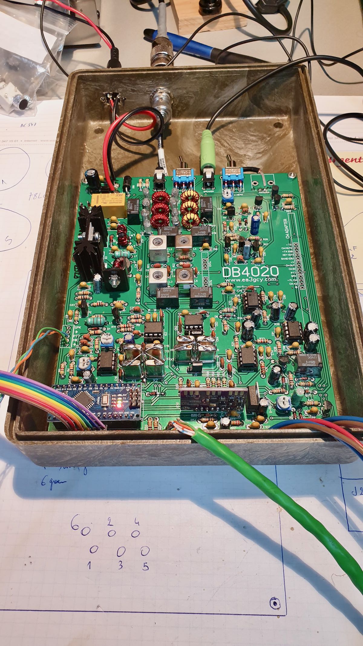
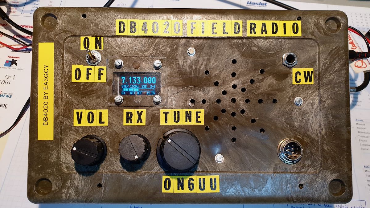
As I’m using a military-grade plastic box, I have to break-out some components like the display, tuning encoder, volume and rx control from the board. I also have put an on/off switch on the box and already have the CW KEY connector ready installed. I also installed a loudspeaker in the box. The SI5351 board and the Ardiuno Nano are the final components which go into the board after installing all wires.
Picture of the board:
I intend to attach a CW paddle to the box made out of a relay. A HWEF tuner (from EA3GCY) which I was planning to incorporate in the box is I think a bit overkill. That HWEF tuner is already in a nice little box and would be a pity to dismantle, also I’m running out of space in the box… Maybe I can fit in a 9-1unun which would then give me good results on both bands…?
Maybe I will install a battery pack in the same box.
The box with board installed:
The box completed front side:
Mind you, it still needs some additional switches for the CW part of the transceiver.
73
Frank (ON6UU)
Frank (ON6UU)



No comments:
Post a Comment