Friday, February 28, 2025
New Product Spotlight: REZ Antenna Posted by OnAllBands
OnAllBands is always excited to introduce new products from the portable ops experts at Texas-based REZ Antenna Systems—a company that continues to think up new ways to make POTA, SOTA, IOTA, and any outdoor operating activities easy, fun, and successful.
DX Engineering customers have had high praise for REZ’s 80-10M Ranger 80 HF Portable Antenna System, calling it “very well made,” “easy to set up,” and “an excellent antenna for field operations.”
See reviews of the REZ Ranger 80 and Recon 40 High-Performance HF Antenna Coil at OnAllBands.
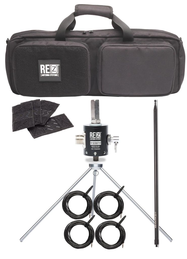
Introducing the REZ Scout Vertical Antenna System
As a worthy follow-up to the Ranger 80, DX Engineering now sells four REZ Scout packages that feature the compact and lightweight Scout Multi-Configuration Antenna System. This versatile portable HF antenna covers 20-6M, boasts impressive handling of 500W SSB/300W CW/200W Digital, is built to withstand the elements, and delivers reliable performance in just about any environment.
Designed for rugged durability, the Scout is CNC-machined from premium 6061 aluminum and finished with a black anodized coating for weather resistance and longevity. Its custom gasket seals the SO-239 connector, providing an extra layer of protection against dust and moisture.
The Scout also includes integrated 4mm radial ports compatible with standard banana plugs, making setup easy and adaptable. Thanks to its patent-pending design, the antenna features an innovative anti-rotation mounting port and a range of optional accessories, allowing for flexible deployment in multiple configurations, including:
- 1/4 wave vertical
- Coil-loaded vertical
- Wire dipole
- Rigid dipole
- Delta loop
The Scout’s mounting port provides versatility and stability in the field. When mounted to a portable antenna mast, it ensures a secure fit, keeping the Scout steady even in variable conditions. When used as a wire dipole, the included hoist ring allows for easy deployment from a tree or other natural anchor points. This setup flexibility lets you quickly raise the antenna to an optimal height.
Choose from these REZ Scout Vertical Antenna System Packages:
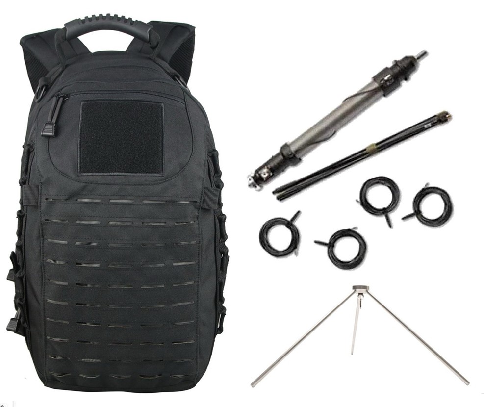
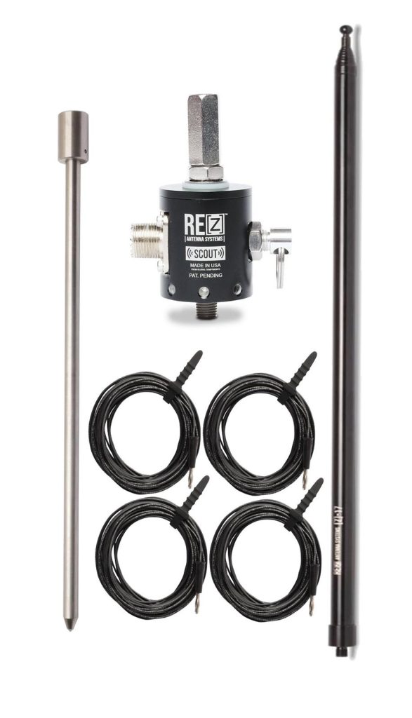
- REZ-SCOUTGS: Includes Scout Mounting Base, 17-inch Ground Spike, Z17 stainless steel 17-foot Telescoping Whip*, and Radial Kit with four 33-foot 18 AWG wires
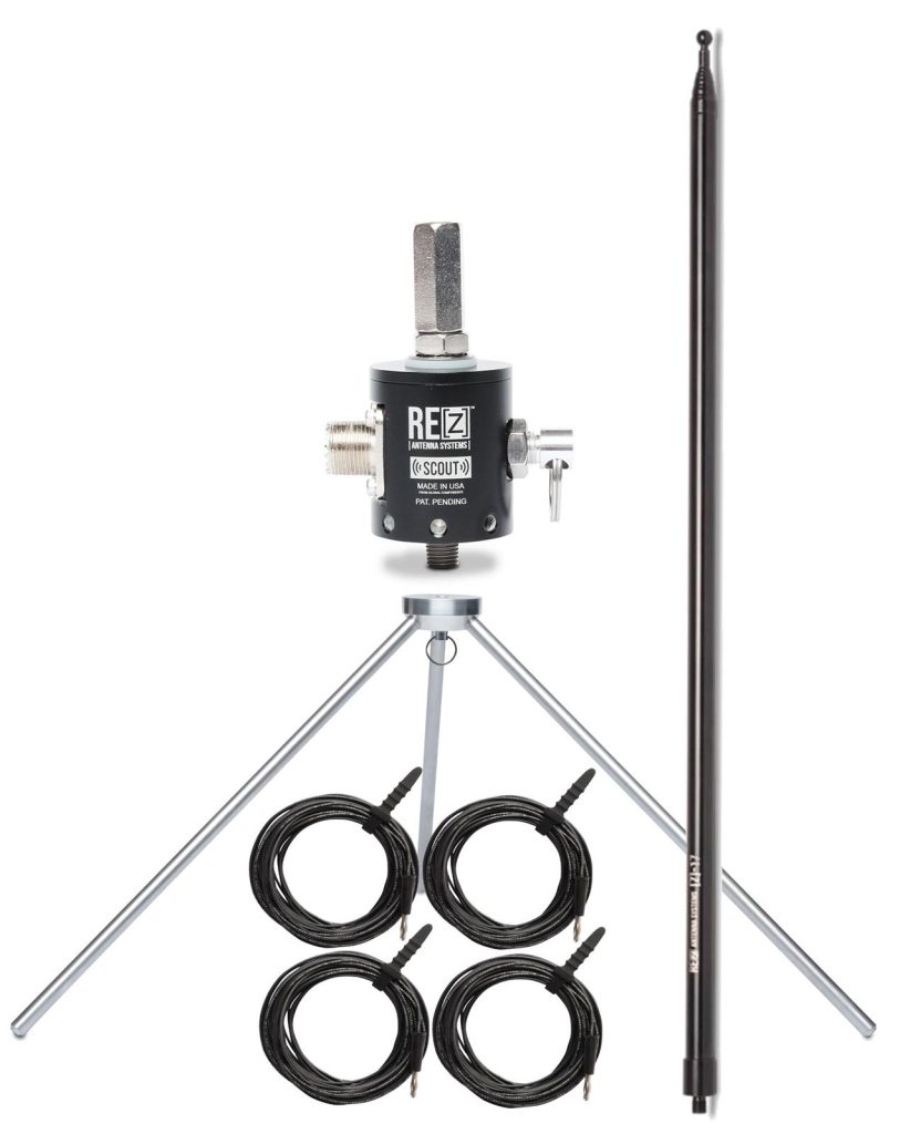
- REZ-SCOUTPD: Includes Scout Mounting Base, ZPOD Aluminum Tripod, Z17 stainless steel 17-foot Telescoping Whip*, and Radial Kit with four 33-foot 18 AWG wires
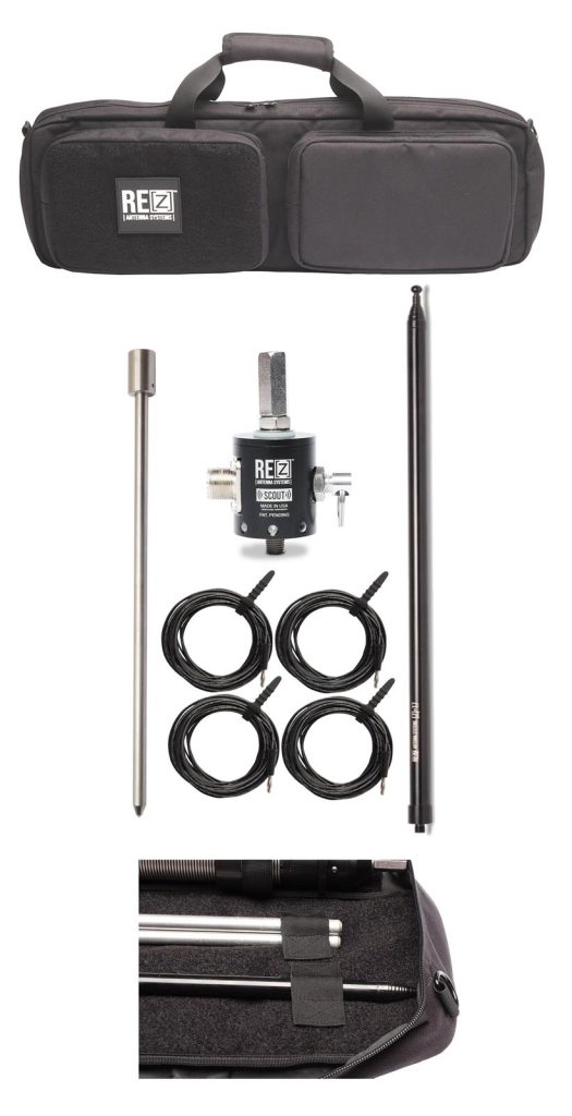
- REZ-SCOUTGS-KIT: Includes Scout Mounting Base, 17-inch Ground Spike, Z17 stainless steel 17-foot Telescoping Whip*, Radial Kit with four 33-foot 18 AWG wires, and FlexPack Antenna Bag
- REZ-SCOUTPD-KIT: Includes Scout Mounting Base, ZPOD Aluminum Tripod, Z17 stainless steel 17-foot Telescoping Whip*, Radial Kit with four 33-foot 18 AWG wires, and FlexPack Antenna Bag
*Extended, the Z17 is a full 1/4 wave on 20 meters. To achieve resonance on higher bands simply collapse the sections, or to work the lower bands (80-40M) pair this whip with a Ranger 80 HF Tuning Coil Assembly (not included).
The REZ SCOUT Mounting Base and FlexPack Antenna Bag are also sold separately.
Find the full lineup of REZ Antenna Systems gear at DXEngineering.com.
Tuesday, February 25, 2025
New Manufacturer Spotlight: CG Antenna Posted by OnAllBands
The DX Engineering 2025 Amateur Radio Products Catalog is only a few months away. As we lead up to its May release in time for Dayton Hamvention®, OnAllBands will be showcasing some of the new manufacturers and their products you’ll find inside.
Today’s featured amateur radio manufacturer is CG Antenna. DX Engineering is pleased to carry the company’s CG-3000 Remote Automatic Antenna Tuner, CG-CTU Tuner Control Unit, and BL-49 UNUN.
CG Antenna CG-3000 160-10M Remote Automatic Antenna Tuner
This weatherproof tuner works for long wires, verticals, dipoles and other amateur, MARS, or CAP operations between 1.6 to 30 MHz. Like the well-known legacy SG-230, this tuner is primarily intended to feed wire antennas or monopoles.
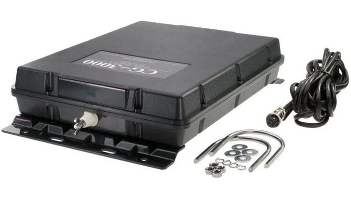
The antenna wire connects to the unit’s high-voltage standoff insulator stud. A UHF female SO-239 connects the station coax, and a ground stud may be used for a counterpoise or an earth ground. The tuner has an impedance range of 12 to 1,000 ohms with maximum power handling of 200W PEP SSB/40W FT8. The minimum required antenna length is 8 feet for frequencies above 6 MHz, and at least 26 feet for 1.8 MHz and up. With a small fiberglass pole and some wire, a good all-band antenna can be constructed within minutes.
The CG-3000 is automatically activated with a low-power carrier. Low SWR tuning results are stored in non-volatile memory, and new tuning attempts on similar frequencies are amazingly fast. The CG-3000 uses a Pi network design which has the advantage (as compared to L networks) of providing low-pass filtering to reduce spurious emissions.
The tuner has a four-pin connector on the bottom panel for the included 16-foot control cable to supply the required 13.8Vdc at 2A (power supply not included). An additional control cable is not required. The solid plastic clamshell case protects the tuner for all-weather outdoor use. Attached brackets and 2.16-inch-width U-bolts and hardware are included.
CG Antenna BL-49 UNUN
This outdoor HF antenna feedpoint transformer is particularly suitable for building an end-fed half-wave (EFHW) antenna. It’s built with heavy-gauge wire and a large toroidal ferrite core which handles up to 600W PEP over the entire range from 1.8 to 30 MHz.
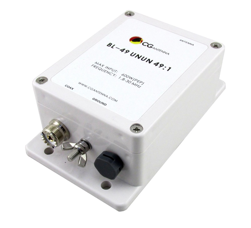
The UNUN’s waterproof case is made from high-strength plastic and features a special valve to drain off condensation while preventing insects from getting inside. A stainless steel eye-hook at the top provides an attachment point for a support rope to handle the UNUN, antenna wire, and coax. Also on top is a stainless-steel stud and wing nut for the antenna wire. Another wing nut allows for the installation of an optional counterpoise wire or ground connection.
End-fed half-wave antennas (EFHW) are very popular because they are easy to hang in limited space installations while achieving multiband functionality with a transceiver built-in tuner or an external wide range tuner. In many cases the use of a BL-49 UNUN with a specific monoband wire length can achieve low or reasonable SWR on many harmonically-related amateur bands.
The radiation pattern of an EFHW antenna is similar to that of a dipole, and the 49:1 UNUN adapts to different end-fed wire configurations: antenna wire suspended straight and parallel to the ground, angled as an inverted-V or inverted-L, or run diagonally as a sloper, with the BL-49 UNUN feedpoint located anywhere from a few feet above the ground to hanging high from a support.
Experimentation is encouraged with this very adaptable and forgiving feedpoint method. See antenna texts and web forums for wire lengths known to provide the best results, such as 60-70 feet for 80-10 meters.
Also check out this article, “Feeding End-Fed Antennas,” by OnAllBands blogger Ward, NØAX.
CG Antenna CG-CTU Tuner Control Unit
The CG-CTU is a handy option for use with a CG-3000 Remote Antenna Tuner (above). It supplies the CG-3000 remote tuner with power and a way to trigger the tuning process remotely. It offers an ON/OFF power switch and a TUNE button, both with LED indicators. The device includes a 32.8-foot control cable—a four-wire connector cable assembly that links the CG-CTU to the CG-3000.
The CG-CTU includes a tuner interface and power connection for Icom transceivers (a 39-inch cable with a plug for the Icom tuner socket.) The tuner is supplied with power via the radio, and the tuning process can be triggered via the Icom transceiver’s TUNE button.
The CG-3000/CG-CTU combination also works with all other transceivers with an included connector cable that serves as a DC cable for connection to the station 13.8Vdc power supply.
Visit DXEngineering.com for more details on the lineup of CG Antenna products.
The Supreme Art of War - LewRockwell
How to stay warm outside in all weather by Ellie Bixler

Getting outside and immersing yourself in nature is one of the best ways to beat the winter blues. Regardless of where you live, there are so many benefits to wintertime hiking and backpacking: the beauty of the snow-covered wilderness, quieter less populated trails, and no mosquitos!
Fear that discomfort and difficulty will accompany cold and inclement weather often keeps hikers inside for the winter. But this does not have to be the case! In order to stay safe and maximize your enjoyment, it’s important to arm yourself with the knowledge of how to stay warm outside on the trail and in your tent. Here are some pro tips and guidelines I like to consider when planning my own cold-weather adventures!
There's no Such Thing as Bad Weather, just bad gear

Staying Dry
One of the most essential strategies in how to stay warm outside is simply staying dry. When exercising, as much as 85% of a person’s body heat can be lost through sweat. In the summertime, this is a great thing! But in wintertime, if the sweat stays near your skin, it will transfer heat away from your body, keeping you cold and soggy. Your goal should always be to minimize moisture and when it happens, wick it away from your body as quickly as possible. To do this, properly layer and bring a change of warm, dry clothes for when you get to camp.
What to Wear
Knowing how to stay warm outside starts with choosing the right materials for your clothing. Most seasoned hikers have heard the phrase “cotton kills.” This is because, unlike wool or synthetic fabrics, cotton clothing tends to hold on to moisture for a very long time, keeping you cold and uncomfortable. When choosing your outdoor clothing, look for materials that move moisture away from your skin and dry quickly, such as merino wool, bamboo, polyester, and nylon. For socks, thin merino wool is the most popular and comfortable option to keep your feet warm and blister-free.
Layering
Because your level of exertion (and therefore heat production) changes throughout a hike, it is important to use a layering system to accommodate changes in body temperature. Even in the coldest temps, one too many layers can cause you to overheat. Your goal is to stay comfortable without causing yourself to sweat. Make sure nothing is too tight, as this can reduce circulation to your extremities. A typical layering system looks like this:

Base layer: Wicking, synthetic, and light, something to pull moisture away from your skin. (Don’t forget; this includes underwear!)
Midlayer 1: Ideally a lightweight yet warm hoodie, pullover, or zip-up. Polyester fleece, wool, or synthetic material. This is your insulating layer! It should be loose enough to fit comfortably over your base layer, but thin enough to keep your outer layers comfortable.
Midlayer 2: An insulated coat or jacket. While not always necessary, this layer is essential in the coldest temps. Down or synthetic insulation are both acceptable, but if you are worried about rain or snow, synthetic stays warm even when wet!
Outer layer: A waterproof shell. Raincoats work great! Try to find something with a hood to protect your head and ears. Ideally, this layer will be made from a breathable waterproof fabric (such as Gore Tex) to prevent sweat condensation.
Cover as much skin as you can! Don’t forget mittens, gloves, a neck gaiter, and a warm hat. Knowing how to stay warm outside comes down to protecting every exposed area of your body.

Water
Staying hydrated is critical to the body’s temperature regulation and circulation, as cold temps make it harder to recognize early signs of dehydration. Even when you aren’t sweating, your body is losing water through the skin, which is exacerbated by the dry winter air. Aim to drink around half a liter per hour while hiking, or 3-4 liters per day. At camp, making hot water, tea, or hot chocolate to sip on can be a great way to keep your core temperature up even in freezing conditions.
Food
Your metabolism is your body’s furnace, and in colder weather, it is important to eat frequently to keep it properly fueled. Proper nutrition is a key component of how to stay warm outside. On a winter hike, your body can use as many as 50% more calories than it would on the same hike in warmer weather, so plan accordingly! While on the trail, it’s nice to have easy-to-access snacks with a mix of healthy fats, protein, and simple carbs. Before bed, eating slow-burning, high-fat foods gives your body the energy it needs to keep you warm throughout the night.
Movement
Movement plays a crucial role in staying warm. Physical activity helps generate heat and improves circulation to your extremities. Staying active is easy while hiking but can be a challenge at camp. You may be tempted to stay glued to the campfire, but if you’re feeling cold, try to incorporate movement and get your heart rate up however you can: stomp your feet, do jumping jacks, or have a silly dance-off. Staying active is an important element of how to stay warm outside, especially in frigid temperatures.

Sleeping Warm
Follow these steps to stay warm inside your tent and sleeping bag when temps drop:
- In cold temperatures, the moisture from your breath can condense and freeze as you sleep. It can be tempting to snuggle all the way into your sleeping bag at night, but make sure you are breathing out of the bag to avoid moisture accumulating inside! This is the case for your tent as well. Make sure you allow for some ventilation, so the moisture can escape the tent and keep you and your belongings dry.
- If you need to go, go! I know the last thing you want to do is leave your cozy sleeping bag in the middle of the night to use the bathroom, but your body works hard to keep urine warm, and that is energy better spent keeping YOU warm. It may be difficult in the moment, but peeing when you need to is important for long term comfort.
- Sleep with a warm water bottle! Before bed, heat up some water for tea and use the rest to make a hot water bottle for your sleeping bag. Cover it with a sock to protect your skin, and sleep with it at your core. This is one of my favorite tricks for staying comfortable when it’s cold.
- Finally, sleep with your hiking clothes! It’s no fun to wake up and realize you need to put on underwear that froze in the night. To avoid this, sleep with your hiking clothes tucked into your sleeping bag with you, ensuring they’re warm in the morning.
Mastering how to stay warm outside can transform cold-weather hiking and camping into an enjoyable and rewarding experience. By staying dry, layering properly, staying active, and preparing with the right gear, you’ll be able to enjoy winter’s beauty without discomfort.
This Robot Swarm Can Flow Like Liquid and Support a Human’s Weight, Inspired by living cells, the robots flow around objects and solidify into tools and other objects by Shelly Fan
With their bright blue bases, yellow gears, and exposed circuit tops, the 3D-printed robots look like a child’s toys. Yet as a roughly two-dozen-member collective, they can flow around obstacles before hardening into weight-bearing tools that push, throw, twist objects like a wrench—and bear up to 150 pounds of weight.
The brainchild of Matthew Devlin, Elliot Hawkes, and colleagues at UC Santa Barbara and TU Dresden, the robots behave like a smart material that shape-shifts into different load-bearing structures as needed. Each smaller in width than a hockey puck, the robots took inspiration from how our cells organize into muscles, skin, and bones—each with vastly different mechanical properties.
Dubbed “programmable matter” and “claytronics,” the concept of robotic materials has long intrigued science fiction writers and scientists alike. Made up of swarms of robots, they can melt and reform, but once locked into a configuration, they have to be stiff and strong enough to hold weight and pack a punch.
“Making this vision a reality would change static objects—with properties set at the time of design—into dynamic matter that could reconfigure into myriad forms with diverse physical properties,” wrote the team.
The new study, published in Science, showcases a proof-of-concept design. Depending on physical and magnetic forces as well as light signals, the robots can form tiny bridges that support weight, collapse into their flow state, and reform as a functional wrench around an object. Each process is controlled by the robot’s integral design.
“We’ve figured out a way for robots to behave more like a material,” said Devlin in a press release.
Unexpected Inspiration
Modular robots and drone collectives have already impressed the robotics community and millions beyond. Over a decade ago, a thousand-bot-strong preprogrammed swarm collaborated with nearby neighbors to self-assemble into complex shapes. While dynamic, they couldn’t support weight. Other designs have been stiffer and stronger but have struggled to reconfigure without breaking group dynamics.
Achieving both properties was “a fundamental challenge to overcome,” wrote the team. For robotic materials to become reality, they need to dynamically shift between a flowing state, in which they can take on new shapes, and a solid state once they reach their final shape.
Nature provides inspiration.
The Power of Three
The team tapped into recent insights gained from the study of embryonic tissues. Starting as a bunch of uniform cells, these tissues can rearrange themselves into multiple shapes and flow to heal tissues. Responding to a bath of biochemical signals within the body, they eventually form a variety of structures—stretchy muscles, stiff bones and teeth, elastic skin, or squishy brains.
“Living embryonic tissues are the ultimate smart materials,” said study author Otger Campàs.
Their versatility relies on three main features.
The first is the force between cells. Imagine being on a completely packed bus. Getting off requires you to push a path across multiple people. Cells are the same. Squishing past each other lets each control where they are in space and time based on their genetic instructions.
The second is coordination. To avoid cellular mayhem, cells use a bunch of biochemical signals to share their positions and movements as they lay out the general landscape of a developing embryo. Finally, cells can grab onto each other—dubbed cellular adhesion—with different levels of strength to build a vast library of tissues with different physical properties.
The robots’ design capture each of these features in 3D-printed hardware.
The bottom of each robot features eight motorized gears dotting the exterior. The bottom isn’t perfectly circular. Some sections are carefully carved out, so that neighbors can always grab onto each other and easily slide off without getting jammed—even when tightly packed. These are a bit like the grooved lids of peanut butter jars. Each gear only slightly peeks out of the housing, enough to grab onto another robot but also easily release it when needed.
To mimic biochemical signals, the team turned to light. Each robot is equipped with light sensors on top and a taped-on polarized film, similar to the material lining some sunglasses. These filters only let light waves vibrating in a particular direction to pass through to the light sensor, telling the robots which way to spin their gears.
Lastly, magnets in small chambers are distributed across the robots’ edges. These can freely roll around and stick to neighboring robots regardless of their position, mimicking cell adhesion.
Robots, Assemble
The team manufactured roughly two dozen battery-powered robots and challenged them to a series of tests. The robots weren’t autonomous: The scientists controlled both the grip strength of the gears and the light signals.
One test started with two towers of robots rotating along each other until they transformed into a rigid bridge. Another began with the robots in a diamond shape that then stretched horizontally into a “mover” that could push a five-pound barbell.
Another test roughly mimicked a workout for your arms. Roughly 20 bots held up two five-pound weights on each side and relaxed only one side when prompted, collapsing into a fluid-like state. All the while, the other side stayed strong.
Even more impressively, the robots swarmed around a nail and solidified to hold it in place. They also hugged a triangle-shaped object in their liquid form and transformed into a wrench capable of twisting the object around. In a demonstration of strength, a collective of 30 robots actively supported a human, weighing roughly 150 pounds, as they stepped across. Then, on command, the structure gradually gave way like mud.
These experiments revealed a surprising quirk. The robots could more easily turn into a fluid-like form when the forces between the robots fluctuated slightly. In contrast, constantly pushing against each other resulted in a deadlock, where no single unit could move, torpedoing the overall dynamics of the robots.
The force fluctuations also saved energy. Returning to the bus analogy, it’s a bit like how wriggling out of a tightly packed human barricade is easier than trying to strong-arm your way through. Adding these fluctuations could be especially beneficial for robots with limited power resources, such as those that run on batteries.
For now, the robot collective has only been tested in about two dozen physical units. But computer simulations of roughly 400 suggest their physical dynamics remain the same and the setup is scalable.
The team is envisioning miniaturizing the system. They’re also eager to explore the technology in soft robots. Like living cells, each unit would be able to stretch and change its shape or size. Although these robots would likely be limited by material properties, a swarm could still significantly change the overall structure and flexibility of any final architecture.
Add in a dose of state-of-the-art control methods—such as AI—to further fine-tune how the units interact and the results could “lead to exciting emergent capabilities in robotic materials,” wrote the authors.
Monday, February 24, 2025
PNP Transistor Radios — What your father knew but didn't tell you by Vasily Ivanenko
Emailers have encouraged me to publish my off-cuts. About 50% of my ideas fail. This is a tough hobby grasshopper. I first chose to not publish my VHF PNP experiments from 2024 because few people ever make PNP transistor circuits -- and as the kids say; "like - who cares?". Perhaps no one indeed. But here goes.
I love PNP circuits and the rich history they hold as radio transitioned from tube (valves for you Brits) to solid state design.
Solid state amateur home brew is ancient craft
In the 1960s, using small signal germanium transistors, home brewers were making single side band suppressed carrier transmitters + also receivers with crystal filters, phase-shift networks, & even Weaver networks. Nothing new under the sun?

Above — Click to see a solid state complete 40 meter band SSB transceiver using a Collins mechanical filter for IF filtration. The A01 transistor and all others were PNP. Still, they got it done without all the fancy programs and test equipment we've got today. I feel humbled by old circuits like this. These images came from a printed book called the Transistor Radio Handbook. This serves as my all-time favorite radio book to read since forever. Someone has it online here. I treasure my printed copy.

Above — Inspired by this Figure, I decide to make a low current, PNP RF preamplifier for my battery operated weather receiver at 162.55 MHz. Please read - the Philco 2N1742 datasheet - an fT of 150 MHz -- and whoa, look at the current gain. I'll use a few more modern silicon BJTs in my design lol.
I love silicon transistors -- although I once build a custom fuzz 'stomp box' for a professional guitarist using germanium transistors when I served as his (tube) amp tech.

From reading the Transistor Radio handbook, even in the 1960's, home brew players had enough common sense to stick their projects in metal boxes and understood how to bypass and decouple their circuits. Somehow, despite easy summations like Mark Montrose's book above, some modern analog builders seemingly feel that the laws of physics don't apply to their projects. Curious.

Input Tank Circuit

Above — Sweep of circuit adapted to allow assessment & tuning of the input tank circuit.
For the collector coil, I temporarily placed a FT-23-43 ferrite with 10 turns on it in-situ. I shunted that coil with a 56 Ω resistor to give a decent output Z for my sweep circuit. Thus, I knew that the frequency transfer response was due the input circuit. I tweaked the trimmer capacitor so it peaked at 162.55 MHz.
Q1 = MPSH10, a 650 MHz part still surprisingly available in Mouser's catalog for 2025. Even with the "temporary" 56 Ω resistor | coil, this amp provides a power gain of ~ 4.6 dB.
The rest of the circuit

Above — "Rookie mistake". To show what might happen if one decides to not include the 39 ohm 'UHF snubber' resistor on the collector, plus -- not tapping the collector coil as performed in the original schematic.

Above — The transfer function of the original schematic as shown with a MPSH10 BJT. Love this.
Most modern builders would never put a BJT as a low noise amp in a VHF project. Plus they would run a lot of current for a high dynamic range.
BJTS at VHF and above bands in the 1960s led to JFETS -->MOSFETS -->GaAsFETS | MESFETS --> pHEMT and so forth over time. But, today, we are making battery powered radio circuitry & using BJTs circa 1963. Feels refreshing.

Above — What happens when we stick in a 2N3906 PNP? Power gain = 2.4 dB


PNP circuits are really not that different or difficult than NPN circuits. I encourage you to experiment with PNP transistors for fun and learning.
Best to you -- Spring is coming!
The Importance Of Current Balancing With Multi-Wire Power Inputs by: Maya Posch

In an ideal world, devoid of pesky details like contact resistance and manufacturing imperfections, you would be able to double the current that can be provided to a device by doubling the number of conductors without altering the device’s circuitry, as each conductor would carry the exact same amount of current as its neighbors. Since we do not actually live inside a simplified physics question’s scenario, multi-wire powering of devices comes with a range of headaches, succinctly summarized in the well-known rule that electricity always seeks the path of least resistance.
As recently shown by NVidia with their newly released RTX 50-series graphics cards, failure to provide current balancing between said different conductors will quickly turn it into a practical physics demonstration of this rule. Initially pinned down as an issue with the new-ish 12VHPWR connector that was supposed to replace the 6-pin and 8-pin PCIe power connectors, it turns out that a lack of current balancing is plaguing NVidia GPUs, with predictably melty results when combined with low safety margins.
So what exactly changed that caused what seems to be a new problem, and why do you want multi-wire, multi-phase current balancing in your life when pumping hundreds of watts through copper wiring inside your PC?
Resistance Is Not Futile

In the absence of cheap room-temperature superconducting wires, we have to treat each conductor as a combination of a resistor, inductor and capacitor. These parameters set limitations on properties such as how much current a conductor can carry without changing phase from solid to gaseous. The contact resistance between the conductors of both sides in a connector adds another variable here, especially when a connector wears out or the contacts become corroded.
In the case of the 6-pin and 8-pin PCIe power connector, these are based on the Molex Mini-Fit series, with the commonly used Mini-Fit Plus HCS (high current system) rated for 100 mating cycles in tin plating or 250 cycles in gold, and a current rating of 8.5 A to 10 A per pin depending on whether 18 AWG or 16 AWG wire is used. The much smaller connector of the 12-pin 12VHPWR, and equivalent 12V-2×6, standard is rated for only 30 mating cycles, and 9.5 A per pin. It is based on the Molex Micro-Fit+ connector.
The smaller pin size and lower endurance increases the possibility of poor contact, as first demonstrated with the 12VHPWR connector back in 2022 when NVidia RTX 40-series cards experienced run-away thermal events where this power connector on the GPU side melted. Subsequent research by the team at Gamers Nexus showed this to be due to poor contact within the connector with resulting high resistance and thus a massive thermal hot spot. Following this event, the 12V-2×6 update to 12VHPWR increased the length of the power pins and decreased that of the four sense pins.
The idea behind this change is that by extending the length of the power and ground pins by 0.25 mm and shortening the sense pins by 1.5 mm there’s a higher chance of there being an actual good contact on the ground and power pins when the sense lines signal the GPU that it can start drawing hundreds of watts.
This change did only affect the male side of the connector, and not the cable itself. This made it very surprising to some when after the much higher wattage RTX 5090 GPUs were released and suddenly cables began burning up,with clear melting visible on the GPU and power supply side. What was going on here?
Multi-Phase Balance
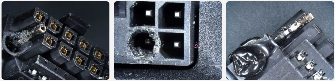
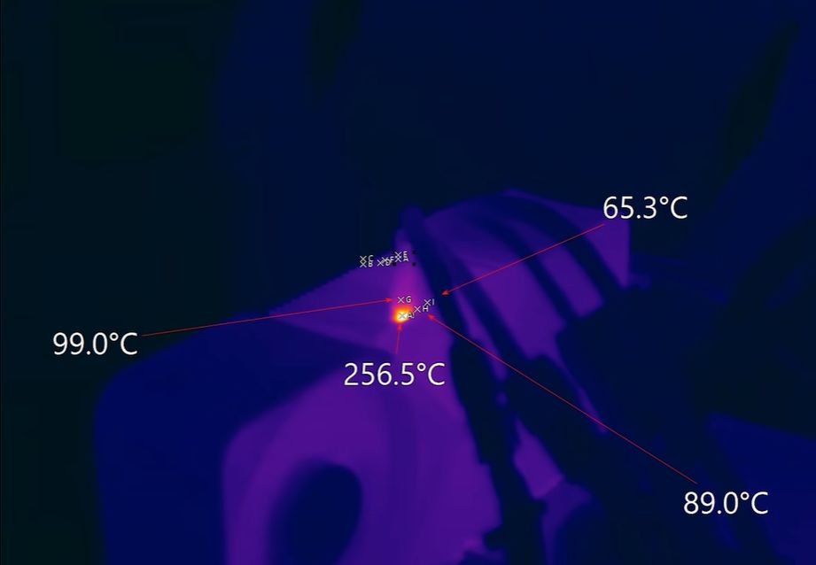
Shortly after the first melting cable event involving an RTX 5090 Founders Edition (FE) GPU popped up on the internet, Roman [Der8auer] Hartung reached out to this lucky person and – since both live quite close – borrowed the damaged GPU, PSU and cable for an investigative video. Involved were not only an RTX 5090 FE GPU, but also the PSU with its 12VHPWR connector. On each side the plastic around one pin was completely melted, with the cable having to be forcibly removed.
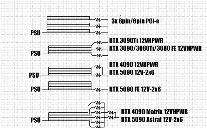
During Roman’s testing with another RTX 9050 FE and 12VHPWR cable he found that two of the six 12V wires were significantly warmer than the rest, courtesy of these carrying over 22 A versus around 2 A for the others while the PSU-side connector side hit a blistering 150 °C. This result was replicated by some and seems to be fully due to how the NVidia RTX 9050 FE card handles the incoming power, by tying all incoming power lines together. This a practice that began with the RTX 4090, but the RTX 5090 is the first to pull close to the rated 600 watts of the 12VHPWR/12V-2×6 connector. This was explained quite comprehensively in a comparison video by Buildzoid.
Because with the RTX 4090 and 5090 FE GPUs – as well as some GPUs by third-party manufacturers – these 12V lines are treated as a singular line, it is essential that the resistance on these lines is matched quite closely. If this is not the case, then physics does what it’s supposed to and the wires with the lowest resistance carry the most current. Because the 12V-2×6 connector on the GPU side sees only happy sense pins, it assumes that everything is fine and will pull 575 watts, or more, through a single 16 AWG wire if need be.
Meanwhile the Asus RTX 5090 Astral GPU does have individual shunt resistors to measure the current on the individual 12V lines, but no features to balance current or throttle/shutdown the GPU to prevent damage. This is actually a feature that used to be quite common, as demonstrated by this EVGA RTX 3090 Ti GPU:
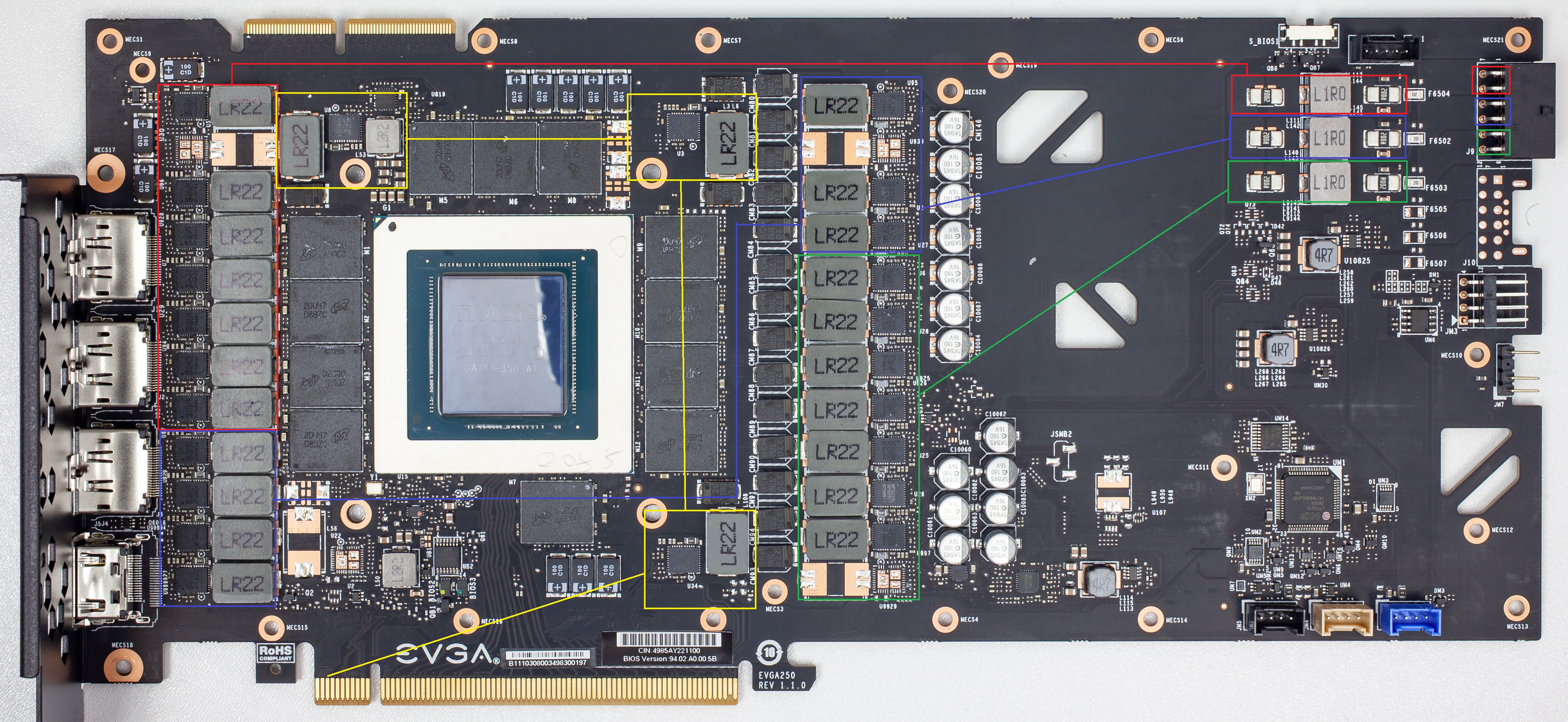
On the top right the triple sense resistors (shunts) are visible, each of which is followed by its own filter coil and feeding its own set of power phases, marked in either red, green or blue. The yellow phases are for the RAM, and are fed from the PCIe slot’s 75 Watt. The bottom right controller controls the phases and based on the measured currents can balance the current per channel by shifting the load between parts of the phases.
This is a design that is completely omitted in the RTX 5090 FE design, which – as Igor Wallossek at Igor’s Lab describes it – has been minimized to the point where crucial parts have begun to be omitted. He also covers an MSI RTX 3090 Ti Suprim card which does a similar kind of phase balancing before the RTX 4090 and RTX 5090 versions of MSI’s GPUs begin to shed such features as well. It would seem that even as power demands by GPUs have increased, crucial safety features such as current balancing have been sacrificed. As it turns out, safety margins have also been sacrificed along with these features.
Safety Margins
The ugly truth about the switch from 8-pin PCIe connectors to 12-pin 12VHPWR connectors is that while the former is rated officially for 150 watts, this power level would be hit easily even by the cheapest implementation using crummy 18 AWG wiring. With the HCS connectors and 16 AWG wiring, you are looking at 10 A × 12 V × 3 = 360 watts, or a safety margin of 2.4. With cheaper connectors and a maximum of 7 A per wire it would still be a safety margin of 1.68.
Meanwhile, the 12VHPWR/12V-2×6 with the required 16 AWG wiring is rated for 9.5 A × 12 V × 6 = 684 watts, or a safety margin of 1.14. In a situation where one or more wires suddenly decide to become higher-resistance paths this means that the remaining wires have to pick up the slack, which in the case of a 575 watt RTX 5090 GPU means overloading these wires.
Meanwhile a 8-pin PCIe connector would be somewhat unhappy in this case and show elevated temperatures, but worst case even a single wire could carry 150 watts and be happier than the case demonstrated by [Der8auer] where two 12V-2×6 connector wires were forced to carry 260 watts each for the exact same wire gauge.
This is also the reason why [Der8auer]’s Corsair PSU 12V-2×6 cable is provided with two 8-pin PCIe-style connectors on the PSU side. Each of these is rated at 300 watts by Corsair, with Corsair PSU designer Jon Gerow, of JonnyGuru PSU review fame, going over the details on his personal site for the HCS connectors. As it turns out, two 8-pin PCIe connectors are an easy match for a ‘600 watt’ 12VHPWR connector, with over 680 watt available within margins.
There’s a good chance that this was the reason why [Der8auer]’s PSU and cable did not melt, even though it clearly really wanted to do so.
Balance Is Everything
Although it is doubtful that we have seen the last of this GPU power connector saga, it is telling that so far only GPUs with NVidia chips have gone full-in on the 12VHPWR/12V-2×6 connectors, no doubt also because the reference boards provided to board partners come with these connectors. Over in the Intel and AMD GPU camps there’s not even a tepid push for a change from PCIe power connectors, with so far just one still-to-be-released AMD GPU featuring the connector.
That said, the connector itself is not terrible by itself, with Jon Gerow making the case here quite clearly too. It’s simply a very fiddly and somewhat fragile connector that’s being pushed far beyond its specifications by PCI-SIG. Along the way it has also made it painfully clear that current balancing features which used to exist on GPUs have been quietly dropped for a few years now.
Obviously, adding multiple shunts and associated monitoring and phase balancing is not the easiest task, and will eat up a chunk of board real-estate while boosting BOM size. But as we can see, it can also prevent a lot of bad publicity and melting parts. Even if things should work fine without it – and they usually will – eating into safety margins and cutting components tends to be one of those things that will absolutely backfire in a spectacular fashion that should surprise absolutely nobody.
Featured image: [ivan6953]’s burnt cables.
Tagged current draw, post-mortem