When the project of building a very small transceiver was accomplished 4 years ago, I still lacked lots of skills in setting up electronic circuits using SMD technology. The radio’s craftmanship had been more or less defective to a certain degree (there were still lots of things to learn when using SMDs on Veroboards), the inside looked comparatively “messy” and the performance was not sited in the premium league. Particularly the receiver was prone to IMD problems when signals on the band were strong. But because I liked the outer appearance of the radio a total revision of the inside had to be performed.
The major changes that were used to improve the radio are:
- Usage of a Si5351 clock oscillator as VFO and LO instead of an Xtal controlled LO and AD9835 as VFO,
- Only one SSB filter (commercially made) instead of 2 ladder filters,
- Dual-Gate MOSFET as 1st mixer (instead of SA612),
- 2SC2078 as push-pull pair in the final TX stage,
- All SMD components are now mounted to the underside of the board,
- TBA820M instead of bipolar equipped push-pull audio amplifier,
- Cabinet size has been enlarged slightly (about plus 0.5 cm in length),
- Proper cabling instead of “spaghetti” arrangement,
- Copper band has been used to improve radio frequency grounding.
Things that were not changed are frequency layout (14 MHz), the ATMega328P microcontroller (MCU) and cabinet size etc.
Even if the changes to the previous version are minor, I had to revise the schematic nearly completely (High resolution schematic):
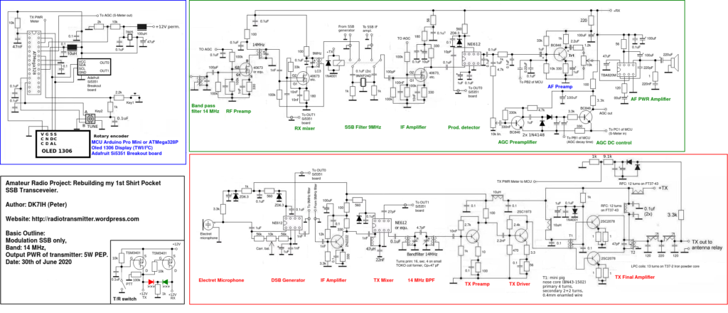
The radio consists of 3 sections:
- Control unit (MCU, Si5351 oscillator, 1306 OLED and related stuff
- Receiver
- Transmitter
Receiver improvements
In the receiver I changed the NE612 into a dual gate MOSFET mixer stage because I found out that the IMD3 was causing problems in the evenings when high signal levels were present. The dual gate MOSFET mixer turned out to be more stable in respect to high signal levels. With the Si5351 being able to produce about 3 Vpp. of rf energy the mixer could be fed with an appropriate signal level.
The MC1350 had been removed because the simplicity of the AGC that section that could also be simplified because only one type of AGC voltage had to be produced. Remember: The dual gate MOSFET and the MC1350 have reverse AGC characteristics, thus an AGC that controls both types of amplifiers has to produce two types of AGC voltage. One rising and one falling when signal levels increase in the receiver.
Transmitter improvements
The microphone amplifier was not necessary because an electret microphone outputs enough audio frequency voltage to drive the NE612 mixer directly. An intermediate amplifier with bipolar transistor amplifies between the SSB filter and the TX mixer pushes the signal to an appropriate level, thus enough energy always is present in the first transmitter stages.
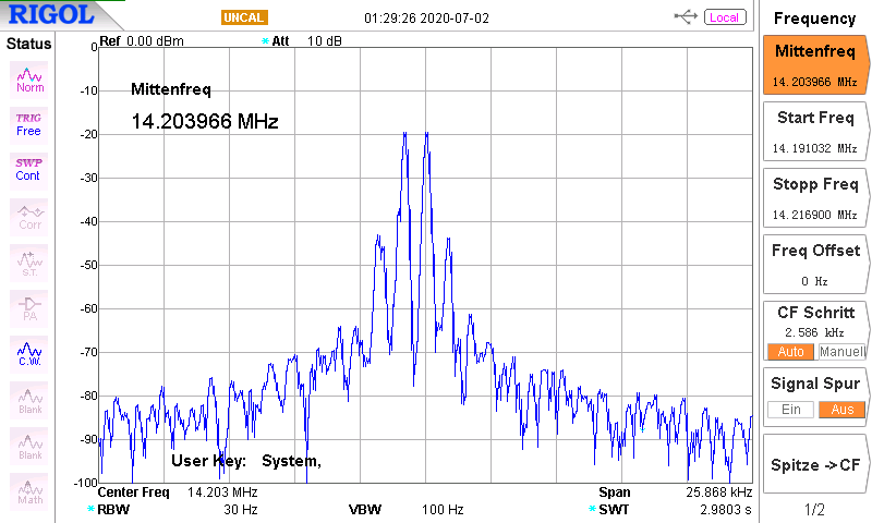
The remaining transmitter has been not changed, only the final amplifier transistors have been replaced with a pair of 2SC2078 (2SC1957 in previous version). Transmit power is now 6 watts (when DC is 13.2 volts from my QRP battery package).
Output spectrum is as follows (Pout = 5W PEP)
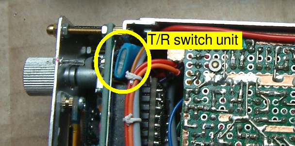
T/R switch
Based on a discussion with WA2MZE here on my blog I tried to minimize physical expansions of a P-channel MOSFET based T/R switch. The basic design can be found here, only two P-channel switching MOSFETs are used.
The circuit is so simple, it fits on a piece of Veroboard just 1 square centimeter in size and put into a piece of heat shrink tubing. After connected to the 12V system it was stored behind the front panel:
The inside has also been straightened (please, don’t say its is still messy!  ):
):
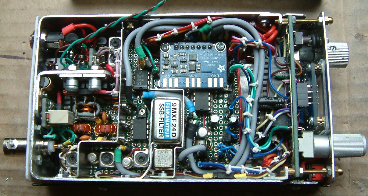
Under the Si5351 breakout the audio amp is hidden. I think available space has been used to the maximum and component density of the board is OK.
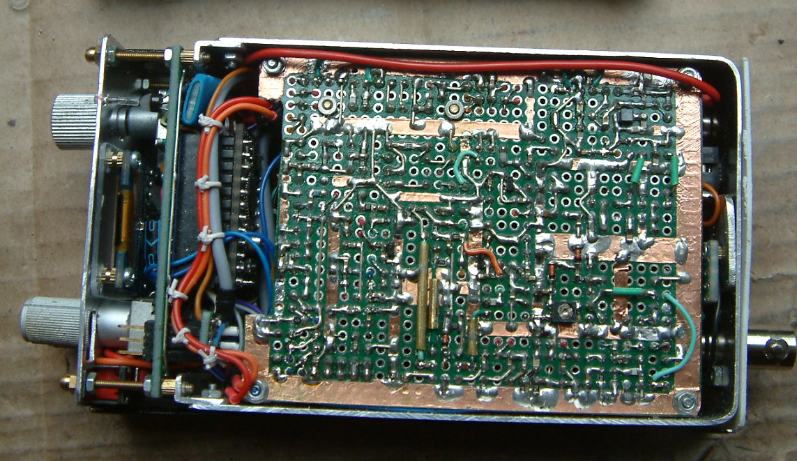
Here a view to the underside where all the small SMD components have been placed:
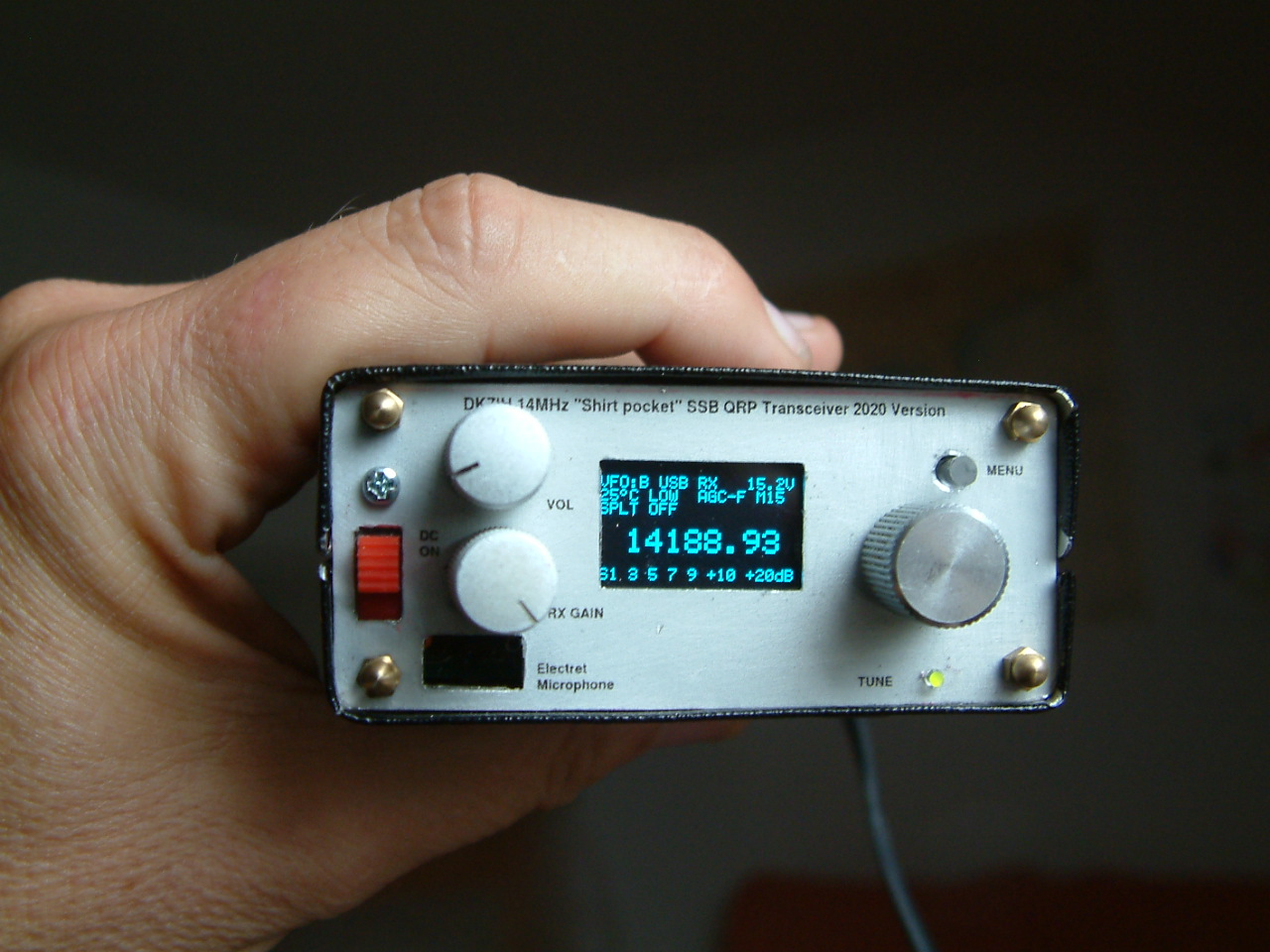
Front panel labeling
Times are getting harder because I’m running short in these adhesive letters that are not available today anymore. An alternative had to be found. Initial tests with the so called “toner transfer method” had been frustrating, but I have found the idea to use labels for laser printers that are cheap and allow individual front panel design.
Here the steps in brief to get a first class front panel labeling:
Step 1: Buy self-adhesive transparency film for laser printers.
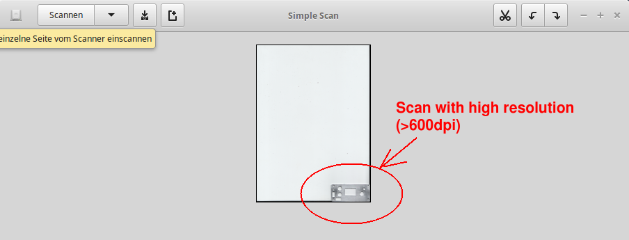
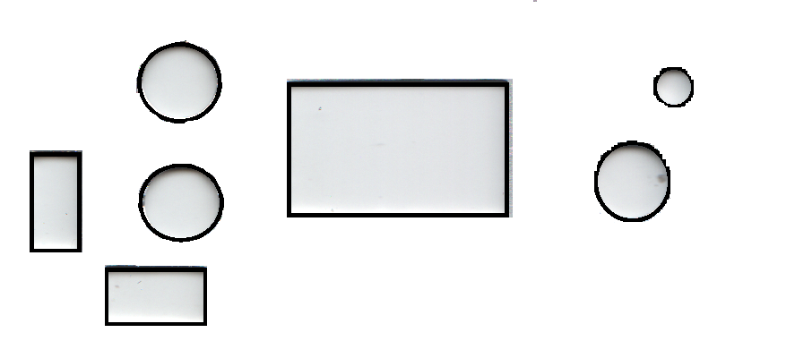
Step 2: Scan your front panel using a flat bed scanner:
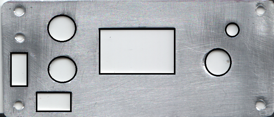
Step 3: Cut the image and work out your front panel. Then enhance the borders of the items you want to label later:
Step 4: Eliminate the background by using the “cut” tool:
Step 5: Put the labels into the right places and later cut out the borders of the items you have just labelled:
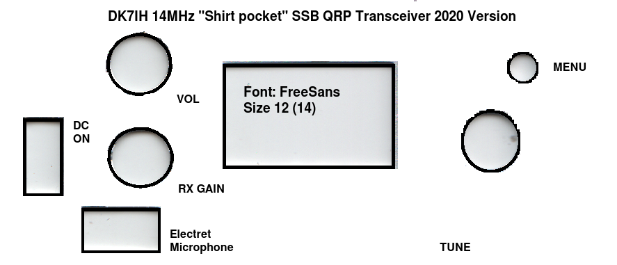
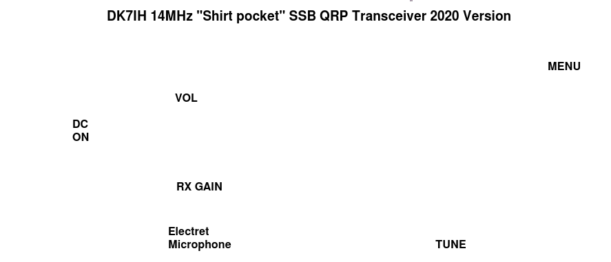
Step 6: Now you are nearly ready to print but one step must be done: Measure the size of your front panel and bring the picture exactly to this size. If you are lucky (like I was) the picture is in the right dimensions. If you are not, you can copy the picture to a text processing software and adjust the size of picture exactly. Make 4 or 5 five copies on the same sheet and print it out with your laser printer.
Step 7: Clean your front board with grain alcohol and fix one copy of the laser print taking the precise position of the label.
Step 8: Cut the holes and other culverts with a sharp cutter knife or scalpel.
Step 9: Be happy because of having made a top quality front panel!
Mechanical construction
Like its predecessor the radio has been mounted into a U-shaped frame of aluminum. Height is 3 centimeters, thickness of the sheet metal is 1 mm. The front panel has been attached with angle plates also made from alu and fixed with M2 screws. This makes a rugged mounting frame for the veroboard and the additional mechanical structures like sockets for antenna, DC supply and headphone.
To finish the cabinet, a base and a top cover from 0.5 mm aluminum sheets have been bent exactly. Precision is now improved because I started a new method: Before bending the sheet metal I cut a wooden block using a precise buzz saw. In this case case exactly 74 millimeters wide (7 centimeters from the inside, plus 2×1 millimeters for the thickness of the mounting frame and another 2 millimeters of space you need because of the minimum bending radius that is required for the metal sheet. Using this method the cover exactly fits onto the mounting frame.
So, that’s the story of another revision of my radios. Thanks for watching!
73 de Peter (DK7IH)
No comments:
Post a Comment