
Last time, we configured the FUSB302 to receive USB PD messages, and successfully received a “capability advertisement” message from a USB-C PSU. Now we crack the PD specification open, parse the message, and then craft a reply that makes the PSU give us the highest voltage available.
How did the buffer contents look, again?
>>> b
b'\xe0\xa1a,\x91\x01\x08,\xd1\x02\x00\x13\xc1\x03\x00\xdc\xb0\x04\x00\xa5@\x06\x00<!\xdc\xc0H\xc6\xe7\xc6\x00\x00\x00\x00\x00\x00\x00\x00\x00\x00\x00\x00\x00\x00\x00\x00\x00\x00\x00\x00\x00\x00\x00\x00\x00\x00\x00\x00\x00\x00\x00\x00\x00\x00\x00\x00\x00\x00\x00\x00\x00\x00\x00\x00\x00\x00\x00\x00\x00'
The zeroes at the end might look non-significant, and they indeed are not with 99.99% certainty – that said, don’t just discard the entire tail end; one of the bytes in the beginning encodes the length of the message. We’ll read those bytes first, and then read only exactly as much as we need, making sure we aren’t reading two messages and interpreting it as one, and that we’re not discarding zeroes that are part of the message.
Today, we will write code that parses messages right after reading them from the FIFO buffer – however, keep this message handy for reference, still; and if you don’t have the hardware, you can use it to try your hand at decoding nevertheless. If you wanna jump in, you can find today’s full code here!
HEADER PARSING
The first byte in the buffer is 0xe0, and it’s not actually part of a PD message that we need to parse – it’s a “start of a message” token, and you can find it in the “RX tokens” section in the FUSB302 datasheet page 29. If you’re looking there and don’t know what SOP is – for our purposes, SOP (without ' or " at the end) means “this packet is for a device at the end of the cable, and not inside of the cable”; we are, indeed, at the end of a cable and not inside one. Further bytes are, however, a meaningful part of a USB-C packet, and that’s where you want to open the PD specification.
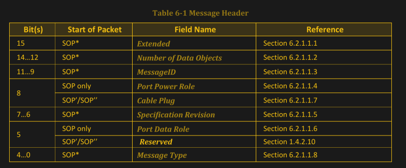
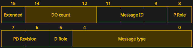
The header is described in the PD 3.0 specification section 6.2.1.1 – page 109. It’s two bytes: in our case, it’s the \xa1a part of the Python’s bytearray representation, 0xa1 0x61 in hexadecimal and 0b10100001 0b1100001 in binary. The first byte contains bits 7-0 and the second byte contains bits 15-8 – you could say, each part of a PD message comes in backwards. The main part we care about is bits 14-12 – take the second byte, shift it right by 4, and mask it with 0b111 to get the message length. In our case, (0x61 >> 4) & 0b111 equals 6.
If the message length equals zero, we have received a control message – those are described in section 6.3, on page 119 of the specification. In the example message, the length is 6. This is not an number of bytes – this is the count of PD data objects, also known as PDOs (Power Data Object). Each of them is four bytes long, and in our case, each of them corresponds to a PD profile. Plus, there’s a CRC at the end of the message, which is four bytes. Thankfully, we don’t need to verify the CRC – the FUSB302 has verified the CRC for us; if the CRC weren’t correct, it wouldn’t put the message into the FIFO for us to read in the first place.
How many more bytes do we need to read, then? We’ve already read three bytes, determining that we have to read six four-byte data objects, and then a four-byte CRC. In total, this message is 31 bytes long. Let’s read the objects first, then read the CRC and discard it. The easiest would probably be reading out of the FIFO four bytes at a time – I’ve read the entire PDO and then split it into messages afterwards in my own implementation.
GETTING THE POWER PROFILES
pdo_count = 6
pdos = []
for i in range(pdo_count):
pdo = i2c.readfrom_mem(0x22, 0x43, 4)
pdos.append(pdo)
_ = i2c.readfrom_mem(0x22, 0x43, 4) # discarding the CRC
Now, we have a list of not-yet-parsed power profiles in pdos – I’ll refer to them as PDOs for brevity. Here, you would do good writing a separate function to parse a PDO, if not for readability reasons alone.
The data message format is described in section 6.4 of the specification, page 129. The first thing you check with a PDO is the data type, bits 30-31, or bits 7-6 of the last byte in the PDO as we receive it. There are four types possible – fixed (the most popular one), battery and variable supply, and the augmented PDO type. We can limit ourselves to processing fixed PDOs for now, and safely ignore the other types.
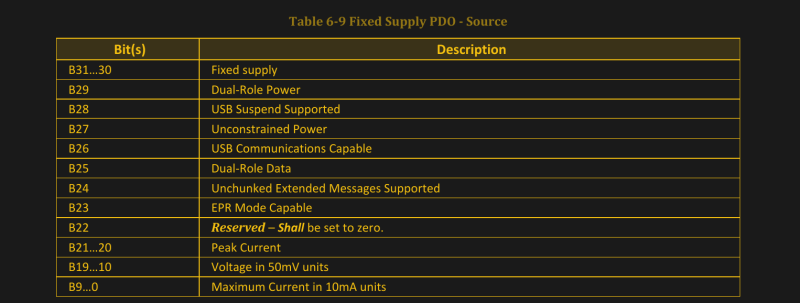
If you start parsing the PDOs already, you’ll notice that we have five fixed PDOs and one extended PDO. I’ll say that this does match the marking on the USB-C power supply I received this message with! Let’s go through the PDO – see page 132 for the table 6-9; it is a very nice table and it has everything you could need. Let’s parse it for the first PDO.
00101100 10010001 00000001 00001000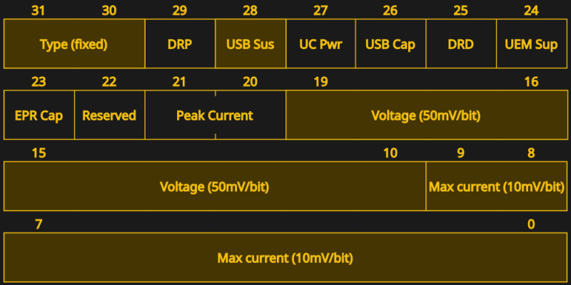
Maximum current is bits 0-9 – so, the two last bits of byte 1, and then the entire byte 0. Voltage is bits 19-10 – four last bits of byte 2, and six first bits of the byte 1. If this is painful to read, refer to this piece of code that parses PDOs in Python. After getting the voltage and current numbers, multiply the voltage by 50 and current by 10, to get millivolts and milliamps respectively.
>>> 0b0100101100 * 10
3000
>>> 0b0001100100 * 50
5000
Oh would you look at that – we’ve got 3000 and 5000, which, as you might’ve guessed, means 5 V at 3 A. PDO parsing function for this part can be found here.
REQUESTING A POWER PROFILE
Now, we have the PDOs – from 5 V all the way up to 20 V. To ask the PSU for one of them, we need to craft a Request message. And remember – to actually get the PSU to provide a higher voltage to us, we need to send our response fast, before the PSU timeouts waiting for a response. Let’s, then, write a function that crafts a response and can automatically reply with it. It’s a four-byte message, with a two-byte header – let’s make a list of six zeroes, modify them in place, and then send them out. Something quick and dirty like pdo = [0 for i in range(6)] will do wonders.
For a start, let’s refer to the header specification – now we actually have to read through fields in the message header and set the ones we need. Again, section 6.2.1.1, page 109! For bits 15-8 (pdo[1]), we only need to change the number of data objects. In our case, it’s 1 – we’re sending a data message with a single PDO request message inside of it. For bits 7-0 (pdo[0]), we need to set the specification revision (bytes 7-6) to 0b11. We also need to set the data message type in bytes 4-0: see the table 6-6 at page 128 for that; in our case, it’s a Request message, with code 0b00010. Oh, and there’s a “Message ID” field that we can now leave at 0, but that you’ll want to increment for subsequent messages. This is all we need out of the header – now, let’s craft the actual request in the four remaining bytes.
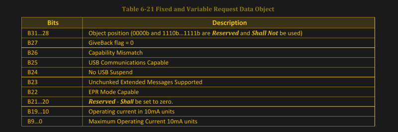
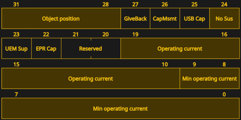
Request messages are described in section 6.4.2, page 141 – you’ll want the table 6-21. In order to request a PDO, we need to know its index – and increment it by 1 before sending. So, 5 V @ 3 A is PDO 1, 9 V @ 3 A is PDO 2, and so on. Let’s go for the 9 V PDO and put 0b010 into bits 31-28. The USB-C PSU will also want to know the maximum and average current we actually plan to consume. Since we’re experimenting, let’s ask for something like 1 A, setting both maximum current (bits 9-0) and operating current (bits 19-10) to 0b1100100. You will also do good setting bit 24 (bit 0 of pdo[5]) to disable USB suspend – just in case.
Now, we have a message! However, we can’t just stuff it into the FIFO. We need to prepend and append two byte sequences that let the FUSB302 know what’s up, known as SOP and EOP sequences (Start and End Of Packet respectively) – consult the FUSB302 datasheet page 29, again. The SOP sequence is five tokens long and essentially transmits a message preamble – three SOP1 tokens, one SOP2 token, and one PACKSYM token; we need to OR the PACKSYM token with our message length in bytes, six in our case, making it 0x86. The EOP sequence is JAM_CRC, EOP (token), TXOFF and TXON. Why these exact sequences, I don’t quite understand, but I’m quite glad I have some open-source PD stacks that I could copy this behaviour from. So, 0x12 0x12 0x12 0x13 0x86 before the packet, and 0xff 0x14 0xfe 0xa1 after.
SOP sequence, packet, EOP sequence – put them all into a FIFO, and we’ll have sent a Request message. The overall worfklow is simple – get capabilities, parse capabilities, pick the one you like, create a Request message, send it, get your voltage. The payoff? You get the voltage of your choice.
A SMIDGEN OF DEBUGGING
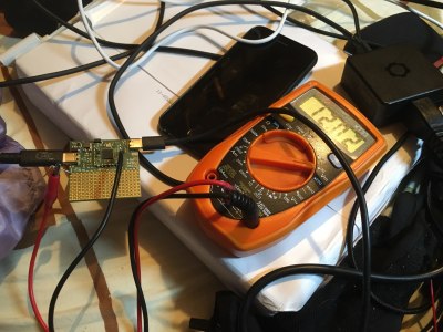
If we didn’t miss anything, probing VBUS will show that you’ve successfully extracted the 9 V profile we agreed to try. If you’re experiencing any hiccups, again, here’s reference code in Python that you can use, and here’s an I2C transmission reference for the Pinecil. Having problems? Here are a few tips.
As is usual with debugging, print() statements will help you quite a bit, until a certain point. On one hand, they’re indispensable, especially if you’re meticulous about converting data to binary or hex representations depending on which one is the most helpful at any debugging point. For instance, you can print the entire packet in hexadecimal, and then print PDOs in binary so that you can check your parsing code.
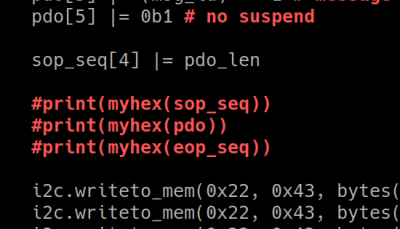
On the other hand, print() statements will interfere with the timing requirements to a surprising degree. Sending data over the console takes a whole ton of time – even if it’s a virtual console, as is the case with the RP2040’s virtual UART over USB-CDC. I’ve spent about two hours debugging this code on a RP2040 and hitting the timeout window all the time, only to find out that I had twenty print statements, and they singlehandedly brought my code from “really fast” to “too slow to respond”. After I commented out the print() statements, my code started working on every PSU I tried it with, and I tacked on a whole ton of custom voltage and current selection logic without any problems.
Checking the receive buffer contents is also useful. After you’ve sent your request, check the receive buffer state – just like in the end of the last article. Is there some data waiting? Read the message out of it, and check the header – is it an Accept message? Refer to page 119 for the code for that one. Nothing in the buffer after a request message? You’ve likely violated the timing requirements.
On the other hand, it’s pretty hard to write MicroPython that is slow enough to violate the timing requirements here. As you make the script more complex, it might be that you spend too much things between receiving the PDOs and sending back a response. Or, perhaps, you get a different kind of message in your receive buffer? Your PSU might be sending out some other message that requires a quick response – perhaps, you’re working with a laptop’s USB-C port, and it wants something else.
9 VOLTS REACHED – WHAT’S NEXT?
 What we’ve done here rivals a PD trigger board in price, it’s way more customizable, likely as cheap if not cheaper than a PD trigger IC, and undeniably way cooler. Oh, and we’ve learned to read and send PD messages – which can and will help you if you’re ever interested in creating anything out-of-ordinary with USB-C. All you need is a FUSB302 chip (about 50 cents apiece), paired with a microcontroller that’s dedicated enough to the task of talking PD – you might already have such a MCU in your project doing something else.
The code is in MicroPython; that said, it’s pseudocode-y enough that it’s easy to port it to a different language from here. If you’re running C++ or C, check the IronOS stack; there’s a STM32 HAL-suited one, an Arduino-suited one, and there’s a decent stack from Microchip. I’ve only seen the former in action; yet, if you don’t feel like MicroPython, I’d wager one of them will be right for you.
Something that you might’ve noticed – at no point did I have to refer to the spooky USB-C state machine diagrams. There are a few states in this code, technically, and state machines are great enough that this code would be improved with one if it were to grow more complex; however, you really don’t need one if all you want is 9 V from a USB-C power supply. The spooky diagrams can, however help you debug things like the 500 ms advertisement-to-response timeout – in other words, don’t be afraid.
From here, you can do a lot of things USB-C. You can turn your barrel jack power supplies into USB-C ones with a bit of extra circuitry, make a supply with wacky custom profiles, explore hidden capabilities of PD controllers, get DisplayPort out of USB-C ports – hell, if you’re pentesting-inclined, you can even create malicious USB-C gadgets.
Here’s my personal simple hack – a short algorithm that picks the best PDO for a static resistance value while keeping maximum current values in mind; solving exactly the scenario where a trigger board fails us. It ties perfectly into the code we’ve written so far, and if you want to develop a high-power USB-C device that does something similar, it might be of interest to you.
You can, and should approach USB-C in a hacker way, and this article is a great example that you don’t need the entire complexity of USB-C PD standard if you want to do useful things with PD – all you need out is ten pages out of eight hundred, and a hundred lines of code.
No comments:
Post a Comment