Coax became popular with hams after World War II when war surplus was plentiful. Hams liked it because it was easy to obtain, relatively inexpensive, and easy to install—much easier than ladder line.
We’ve all got some. Whether it’s for cable TV, satellite, Internet, or ham radio, coaxial cable has become the RF highway for moving signals from one point to another. Fortunately, there are no orange barrels or detours—most of the time. But there are occasions when we need to check, repair, or even replace coax.
DVM Checkup
Materials Needed: Digital voltmeter, jumper with alligator clips and/or SO-239 shorting adapter, dummy load (optional)
The most common and readily available test tool is the digital voltmeter (DVM). Cheaper ones include the basics: voltage, current, continuity, resistance. The more expensive ones add features like capacitance, frequency, amperage, and others. All you need for this checkup are the continuity and resistance settings.
To enter continuity mode, turn the dial to the continuity symbol, which will resemble sound waves or a symbol for a musical note. If you’re using an auto ranging multimeter, you may need to press the “mode” or “select” button a few times until the symbol also appears on your screen.
For testing unconnected patch cords or rolls of coax, touch the multimeter probes on both sides of the cable. Check the shield ends, then the center conductor—if it’s bulk coax without connectors you’ll need to strip the end. If you don’t hear a loud beep, it means there’s a break in the wire or a faulty coax connector.
Stress points on the cable near an antenna rotor or a tight bend can cause the conductor to break, especially with solid wire. Sloppy soldering, or corrosion, on connectors can cause poor connections and problems with your antenna system.
If the cable is already installed, make sure to disconnect it from your radio and antenna—below any matching devices. Things like baluns, ununs, and chokes can cause false readings. For example, a 4:1 balun can read as a DC short on a DVM but operate properly at radio frequencies.
It’s a pain to check a 100-foot coax run that’s already in place—the meter test leads aren’t long enough. Instead, check the cable for an existing short by touching one probe to the center pin and one to the outside of the PL-259 connector at one of the ends. If there’s no beep indicating a short, make it a single conductor by tying together one end, connecting the center pin and outside of connector. The alligator clip jumper will work, but I prefer using a panel mount SO-239 with the center grounded to the pin.
Touch both leads at the remaining end with the DVM leads. If you hear the beep, both shield and center conductor are okay. If not, check your connectors for issues or consider replacing the entire run.
Some prefer to use a similar method with the resistance scale and a 50-ohm dummy load, which substitutes for your antenna. No dummy load? You can use a 47-ohm resistor, which is close enough. When you touch the leads, the 0L reading should change to something in the ballpark of 50 ohms if the coax is okay.
In the next section, you’ll see how to check the cable’s integrity. Sections of the coax you replaced could test okay and possibly be recycled to make jumpers or short runs.
Antenna Analyzer
Materials Needed: Antenna analyzer, coax connector or alligator clip jumper to short the end of cable, velocity factor (VF) numbers for cable(s) you’re testing. Velocity factor can be found at the dealer or manufacturer website.
Most hams use antenna analyzers while building and tuning antennas, but it has other features that will help you measure coax length without a tape measure, calculate loss in dB, and discover its general condition. The examples that follow are based on one popular model, the RigExpert AA-55Zoom, measuring DX Engineering RG-8X 50-ohm Coaxial Cable (DXE-8X). Consult your specific analyzer’s instructions for operation.
Coax Length
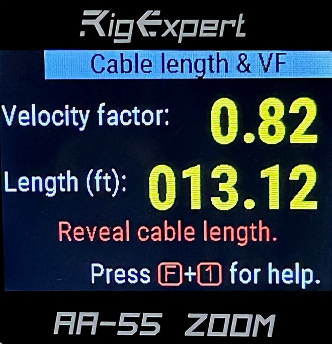
Got some coax but no tape measure? Let your antenna analyzer do the work. On the AA-55, select TOOLS from the menu, then LENGTH & VF. Enter the velocity factor and press OK. Length will appear on the screen in the format you’ve selected (feet or meters).
You can also find velocity factor by entering a known length. The photo below shows the length of a patch cable I randomly selected, calculated by the AA-55.
Loss
The greater the length of coax cable you use, the more signal loss you will have. This is due to a number of factors. Losses within the coax cable itself come from the resistance of the conductors. Dielectric loss represents another of the major losses in most coax cables—the dielectric is the insulation around the center conductor. The loss increases with frequency.
Radiated loss of a coax cable is normally much less than the resistive and dielectric losses. But some very cheap coax cables may have a very poor outer braid, and in these cases will contribute to additional losses.
To find how much attenuation there is in a length of cable, go to the TOOLS MENU and choose CABLE LOSS. You’ll take two measurements, the first with the cable end open and the second with the end shorted. The AA-55 will collect the data and show a graph (below) of the losses in dB. You can change the frequency by moving the left/right arrows.
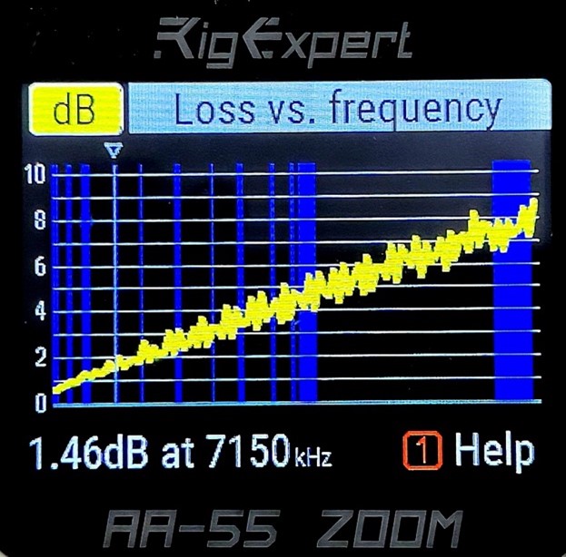
The loss graph shows 1.46 dB attenuation for the 150-foot test cable at 7.150 MHz, which has seen plenty of action at Field Days and Ohio State Parks on the Air (OSPOTA) activations.
Cable Impedance vs. Frequency
To find the impedance in a length of cable, go to the TOOLS MENU and choose CABLE IMPEDANCE. You’ll take two measurements, the first with the cable end open and the second with the end shorted. The AA-55 will collect the data from 100KHz to the maximum frequency on your analyzer and show a graph (below) of the impedance at any given frequency. You can change the frequency by moving the left/right arrows. You’ll notice in this case, it’s very close to the 50-ohm specs.
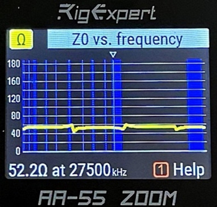
This can help you identify unmarked coax as well as check compliance with the coax specs provided by the manufacturer. It’s also a way to monitor coax condition from season to season. As the sun bakes our coax installed outdoors, impedance and losses will change over time due to exposure.
The Inside Story
It’s not practical to peel back the jacket and shield to examine a length of coax—it would render the cable useless. But tools like the DVM and antenna analyzer will let you check and assess the viability of your coaxial cable electronically to help you make decisions about repairing or replacing.
No comments:
Post a Comment