Installing SWR and RF Power Sensor in uBITX
I modified the I2C Type Signal Meter firmware to display SWR when using Nextion LCD in uBITX.Release I2C Type Signal Meter firmware V0.8, If you want something stable, use V 0.7
(V0.8 is a beta version)
Now if you are using the I2C Type Signal Meter, you do not need to update the uBITX firmware and the Nextion LCD GUI.
You only need to upload the firmware of the I2C Type Signal Meter to V0.8.
I plan to improve the Nextion LCD GUI to take advantage of this feature a bit, but I will keep it compatible with the existing GUI.
1.Creating a Sensor
Any sensor that outputs FWD (Forward) and REV (Reverse) analog can be used.
The voltage from the sensor is recommended to be less than 3 volts.
I have made a simple sensor.
It is a very simple circuit called 'Stockton Bridge'.
I made it in the form of ND6T which is used mostly by Bitx or uBITX users.
http://bitxhacks.blogspot.com/2017/03/nd6ts-forward-and-reverse-power-meter.html
Since there are quite a few PCB pieces, I have imitated the ND6T's SWR Bridge.
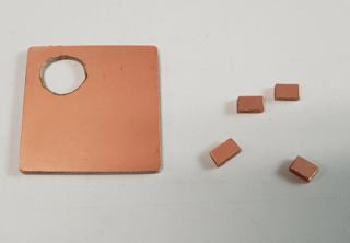
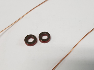
Anything that can use 1 ~ 50Mhz is okay with Core.
'Stockton Bridge' I made two for testing. The two are the same, but the Forward and Reverse outputs are opposite.
If you search for 'Stockton Bridge', 'SWR Bridge', or 'SWR Sensor' on the Internet, you can see quite a lot of things you can easily create.
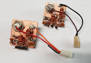
(Be careful of the direction when winding the coil on the core.)
2.Firmware
You can download the firmware file from the link below.
https://github.com/phdlee/dspmeterv1/releases/download/V0.80/CEC_I2C_Meter_V0.8.zip
If you need a source file, please click below.
https://github.com/phdlee/dspmeterv1/releases/tag/V0.80
For more information on how to update your firmware, go to http://www.hamskey.com
3.Connecting to the I2C Type Signal Meter
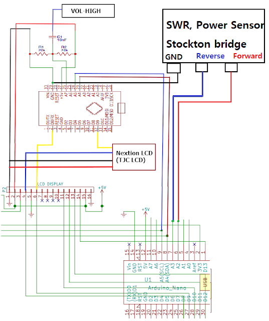
You only need to connect three additional wires to install it.
Connect FWD (Forward) of Sensor to A2 of I2c Meter.
(Red color line)
Connect REV (Reverse) of Sensor to A3 of I2c Meter.
(Blue color line)
Connect GND (Ground) of Sensor to GND of I2c Meter.
(Black color line)
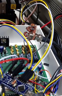
The picture below shows that I connected the white line for Forward, the yellow line for Reverse, and the black line for Ground.
CAUTION: Do not have long wires as shown below. Multiple noise and various problems may occur. Keep the wires as short as possible, It is recommended to use shielded wires.
I have a few uBITXs and below is a uBITX without a Case for development.

4.How to Use
If it is made simple without any shielding as above, 1.5 or less and 3.0 or more are inaccurate. You can increase the precision by using metal shields between Forward and Reverse when creating the sensor.
But I decided to use it as it is. This is enough for a simple SWR meter on a transceiver.
It works the same way as DSP Signal Meter. Therefore, first check if the DSP Signal Meter is operating normally.
The I2C Meter relays the data between uBITX and Nextion LCD.
When there is no data to relay (as IDLE time), the I2C meter measures the signal and transmits it to Nextion LCD.
The I2C Meter will relay the data and will detect that uBITX is in TX state. At that time, the Forward and Reverse signals are read, converted to SWR, and transmitted to Nextion LCD.
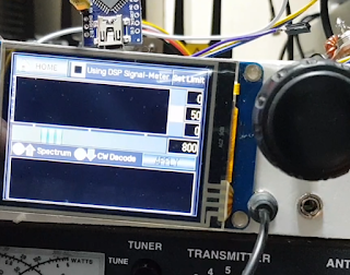
SWR : 1.0 ~ 1.4
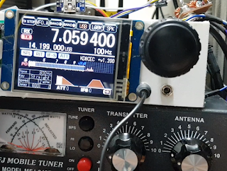
SWR : 1.5 ~ 2.4
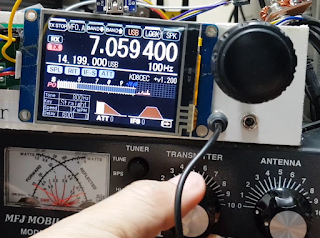
SWR : 2.5 ~ 3.4
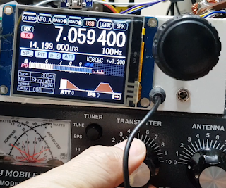
SWR : 3.5 ~ 4.4
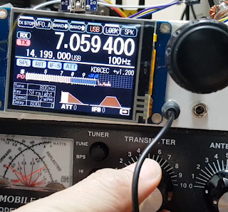
SWR : 4.5 ~ 5.4
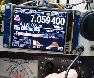
SWR : 5.4 ~
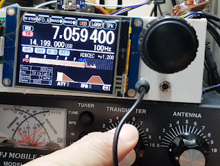
SWR : infinite
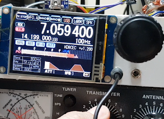
I tested it with MFJ-945 and Diamond SX-600. For SWR 2.5 and above, the two SWR values are displayed quite differently. The sensor I made was more like the one measured on the SX-600
5. Test Video
Thank you for reading
Ian KD8CEC
No comments:
Post a Comment